Showing posts with label smd. Show all posts

Thursday, October 25, 2012

Assemblage Gertboard - CMS

Aujourd'hui on assemble notre Gertboard, l'extension pour le Raspberry Pi, qui nous donnera 12 entrées/sorties protégées, 6 sorties pour relais, 2 pour moteurs, ADC et DAC, et finalement un Atmega328.

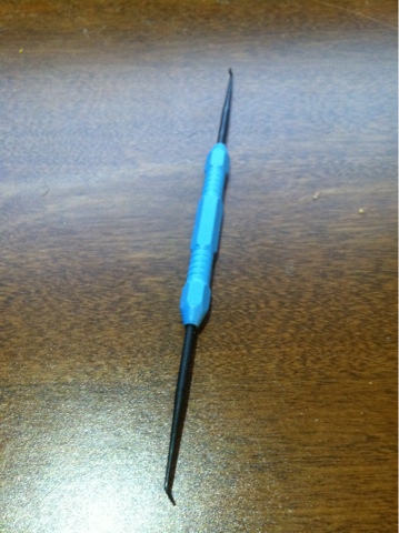
On commence avec les composants CMS (SMD en anglais, voir aussi http://raspberry-python.blogspot.com/2012/10/gertboard-smd.html). Pour cela, je suggère un fer a souder a pointe fine de 12W a 15W, de la soudure fine et un petit outil pour placer et tenir les SMD (on peut aussi utiliser une pincette, une aiguille a crocheter etc):


On pousse en place avec l'outil
Une technique pour souder les CMS est expliquee ici:
http://www.aurelienr.com/electronique/soudercms.htm

Dans mon cas, ce que je fais:

Presque au milieu, le fer a souder vas attirer le composant

Je mets de la soudure sur un cote (le cote droit), je pose le composant presque au bon endroit, mais un peu vers  l'autre contact (cote gauche), et je chauffe encore la soudure du cote droit. Au moment ou ça se liquéfie, le composant est attiré vers le fer a souder. On retire le fer a ce moment, et le composant est maintenant centré. On soude l'autre coté et on est prêt a passer au suivant! Si vous etes pas tres habile, utiliser l'outil pour tenir le composant en place, ou utiliser des pincettes, etc. Consultez aussi la page 6 et 7 du guide officiel d'assemblage. On y trouve des images explicatives.

Le diagramme de la page 11 du guide quant a lui nous indique comment placer les composants. C'est simple a lire du au code de couleurs. Il faut les faire dans l'ordre et ne pas ouvrir de nouveaux sachets avant d'en avoir fini un.

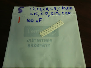
Les 100nF (175=9265)

100nF en C20 (aussi en C2,C3,C8,C9,C10,C11,C15,C17,C19)

100nF en C20,C8,C11 (aussi en C2,C3,C9,C10,C15,C17,C19)

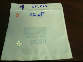
Apres les 100nF, on y va du deuxieme sachet, les 22nF en C12, C13.
On continue:
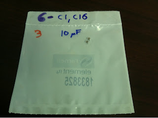
  • 10uF en C1 et C16 (plus gros et donc plus lourds, alors on centre)
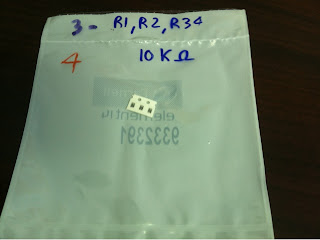
  • 10KOhm en R1, R2 et R34 (cote noir vers le haut)
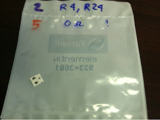
  • 0 (zero) Ohm en R4, R24  (cote noir vers le haut)
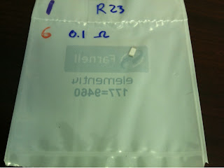
  • 0.1 Ohm en R23 (plus gros, avec numéro vers le haut)

C'est complet:
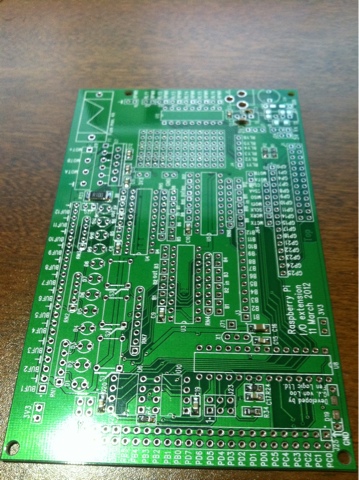
Tout les composants CMS en place!

La prochaine etape


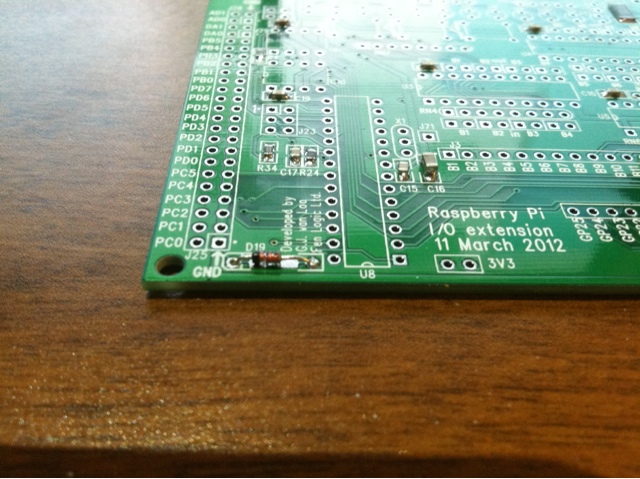
On est prêt a installer les autres composants maintenant. Pour ceux la, on fera la soudure a l’arrière. Par exemple, la diode (avec la barre noire du cote gauche - elle a une orientation spéciale):


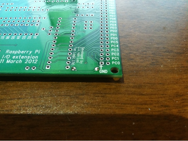
La vue du revers, on voit la soudure de ce cote la:


Je continue plus tard.
Building The Gertboard

The next few posts are going to be in french. They will have a lot of pictures however, so you can still follow. The reason I'm posting in french is that there are no resources available at this time regarding the Gertboard, in french. First will be the SMD components, then the rest, in the same order as the english instructions. I did substitute a few components, basically, different color headers, different color (and size) LEDs etc, but it is fundamentally the same thing. It does illustrate the value of having the Gertboard as a kit though. I doubt I would have even bought one if it had not been available as a kit. Half the fun is building it and tweaking it for your use. Now that I've actually used it, I will build another one, with several more mods and a different DAC. I'll wait until they are back in stock to look into that however.

Wednesday, October 24, 2012

Pocket Mini Computer kit

On my previous post, Blue Screen Of Basic, I was showing the output of a computer mini kit I just built.

What

The Pocket Mini Computer is a simple kit that can be put together in an evening. Just like the Raspberry Pi, it is a bare board (quite like the Apple I). You then need a keyboard (PS/2), monitor (VGA) and power supply (5V, mini USB).

It is not a competitor to the Pi, particularly based on spec and price. It wont run Linux. At any rate, you are probably anxiously waiting on your backordered Raspberry Pi and Gertboard, so that'll give you something to do, hehehe.

Rather, it's something to learn soldering on (or in my case, have fun building stuff, like people do puzzles or crosswords), and play with Propeller Basic and SIDCOG, an emulation of the SID chip including filters using one of the 8 "cogs" (core) of the "processor".

I should really say microcontroller. It runs on a Parallax Propeller microcontroller QuickStart board which is included in the $39 price tag (and that is less than what Radio-Shack sells the P8X32A by itself!)

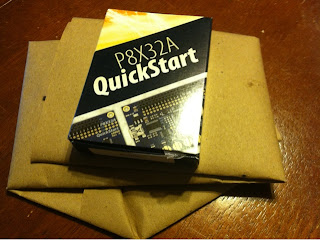
The box


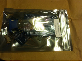
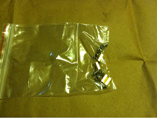
The bags


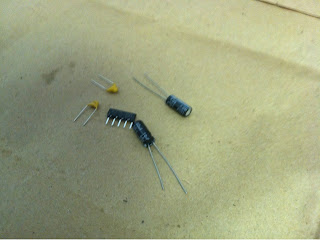
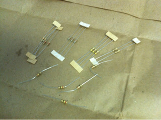
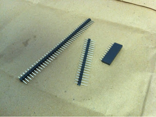
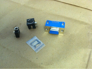
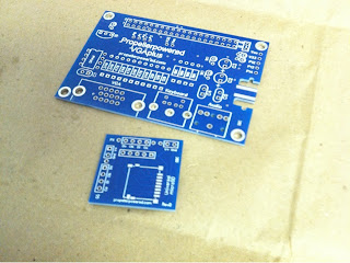
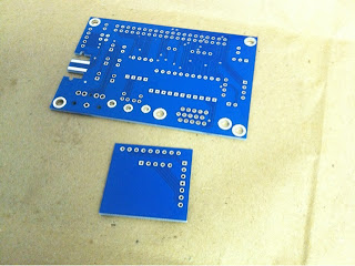
The parts


Bonus

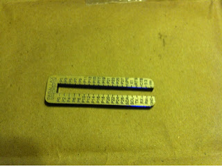
While supplies last, Jeff includes a laser cut acrylic reference block for the P8X32A GPIOs.

Now, let's build this.

Wednesday, October 17, 2012

Gertboard SMD

SMD 1-6 (pg.11: Gertboard_Assembly_Manual_Rev1.1_F.pdf)
 
Farnell/ Element14  175=9265

1759252

1833825

9332391

9333681

177=9460

Number in black on top left corner is reference to installation order for Tandy (Tandy instructions - note that this is slightly different than the element14 kit / procedure)