Showing posts with label diy. Show all posts

Thursday, April 30, 2015

Deadman's Switch

From Wikipedia:
"A dead man's switch (for other names, see alternative names) is a switch that is automatically operated if the human operator becomes incapacitated, such as through death, loss of consciousness or being bodily removed from control. Originally applied to switches on a vehicle or machine, it has since come to be used to describe other intangible uses like in computer software."

NSC-01

For Team Near Space Circus' participation in the Global Space Balloon Challenge with NSC-01, we wanted to make sure that once powered up, and enclosed, we would still have control of the computer cluster and the timeline of events, as to what would happen when. As we devised a network with 7 nodes (see part 1 and also part 2 of the computer network in near space) with a master controller and many slave nodes, we needed a way for the system to wait on a signal from us.

A plain old switch would do the trick of course. But what if the balloon took off and we forgot to flip the switch? Or somebody tripped and let the balloon go? 

Martin DeWitt demoes why we need a deadman's switch

Then the master controller would have stayed in standby mode, sending keep alive frames to the other nodes and we would have had no images, no video, no gps data etc. Not good.


Tethered switch

If you've ever spent any time on a threadmill, no doubt you've encountered a tethered switch. Usually it's a magnetic plug, with a string, terminated by a clip. You clip it to yourself, so if you ever fall down/off the threadmill, you end up yanking the plug off the machine, and it stops right away.
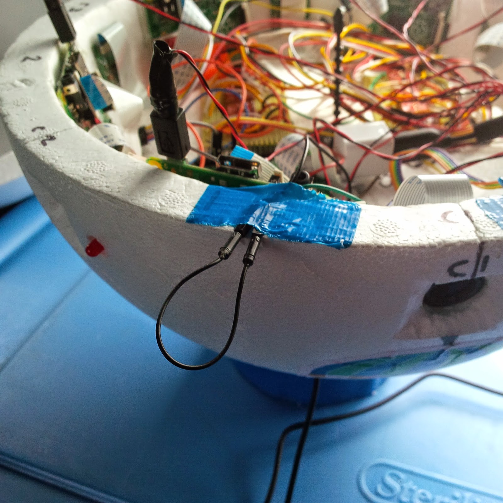
Simple deadman's switch, just needing a string

Since the Raspberry Pi has many GPIO pins, all we needed to do was create a simple circuit between two of them that, once interrupted, would signal that it was time for the master controller to go to work.
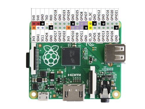
We will need two GPIO pins, how about GPIO17 and 27?
Why two GPIOS? We could have connected a GPIO to 3V3 and GND through resistors (to protect/limit current), to ensure LOW and HIGH modes. But, trying to keep things as simple as possible from a hardware perspective (software doesn't weigh anything, hardware does), using two GPIOs made a lot of sense. Set one GPIO as input, one as output, raise the output HIGH, the input now sees a value of 1. Open the circuit (by pulling the wire out), and the input no longer sees HIGH, it now reads 0.

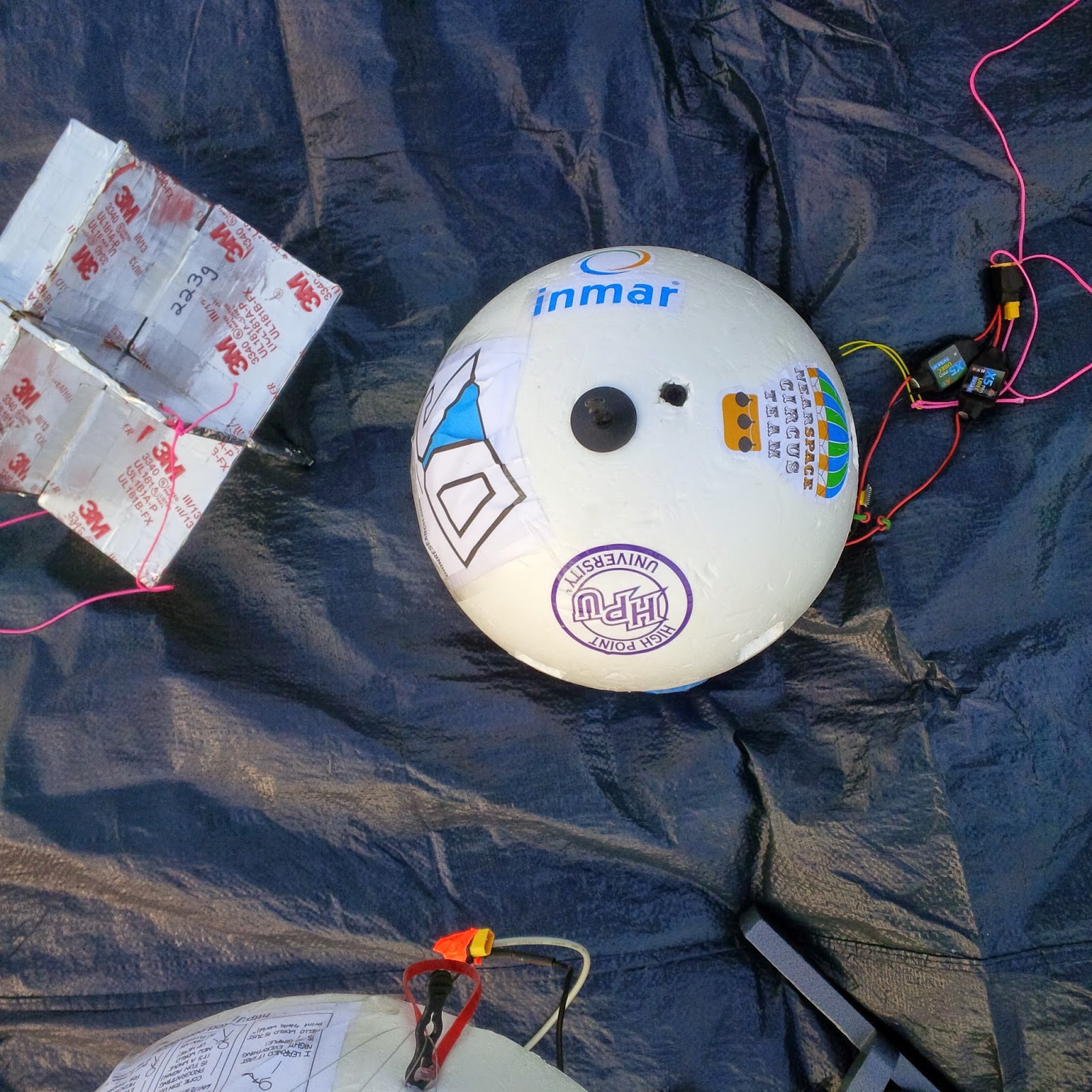
Our sponsors (bottom half of payload) with IR cam
radar reflector on the left, deadman's switch on right w/carabiner

A string attached on one end to the wire sticking out of the side of the payload and on the other end to a carabiner clip is really all that was needed.

Deadman's switch code


We've already covered the serial port, sh and docopt in part 2 of the computer network in near space. If you are wondering about these things (and lines 98 to 101 in the code below) I urge you to go and read that article first. I've left here the core of what is needed for implementing the software side of the deadman's switch. We first need the GPIO module. On line 9, we import it as gpio (because uppercase is usually reserved for constants). Then on line 102 we set up the gpio module to operate in BOARD mode. That means physical board pin numbers. In the field, you can always count pins, but you might not have a GPIO map handy... But if you prefer Broadcom nomenclature there is a mode for that too.


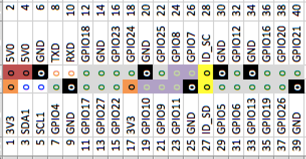
So GPIO17 is the 6th pin on the bottom and GPIO27 is the 7th. Since odd pins are at the bottom and even at the top, this means pin 11 and 13. Line 103 sets up pin 11 to be an output, and line 104 sets up pin 13 to be an input. Finally, line 105 "arms" the deadman's switch by setting pin 11 to HIGH. Pin 13 should now be reading a 1 instead of a 0.

9:  import RPi.GPIO as gpio 
[...]
98:  def main(args):  
99:    my_addr = int(args['<address>'])  
100:    
101:    ser = serial.Serial('/dev/ttyAMA0', 115200, timeout=1)  
102:    gpio.setmode(gpio.BOARD)  
103:    gpio.setup(11, gpio.OUT)  
104:    gpio.setup(13, gpio.IN)  
105:    gpio.output(11, gpio.HIGH)  


We are now going into the actual functionality of the switch. We establish a simple while loop on line 161, reading pin 13. As long as we see 1, the circuit is closed and on line 162 we send a KEEPALIVE frame to the other nodes (see previous article). We also sleep for 1 second on line 163 (no need to poll faster than that). The moment we get a 0, the while loop exits, and before starting the master controller on line 165, we log our launch time on line 164 (the logging aspects will be in a future article).


[...]
159:    
160:    # deadman's switch  
161:    while gpio.input(13) == 1:  
162:      ser.write(KEEPALIVE)  
163:      sleep(1)  
164:    logger.debug("We are launching! (on {})".format(datetime.now()))  
165:    master_controller(ser, counter) # forever controlling the Pi network until I die    


And that is it!

This can be implemented in all kinds of different projects. Have fun with it!
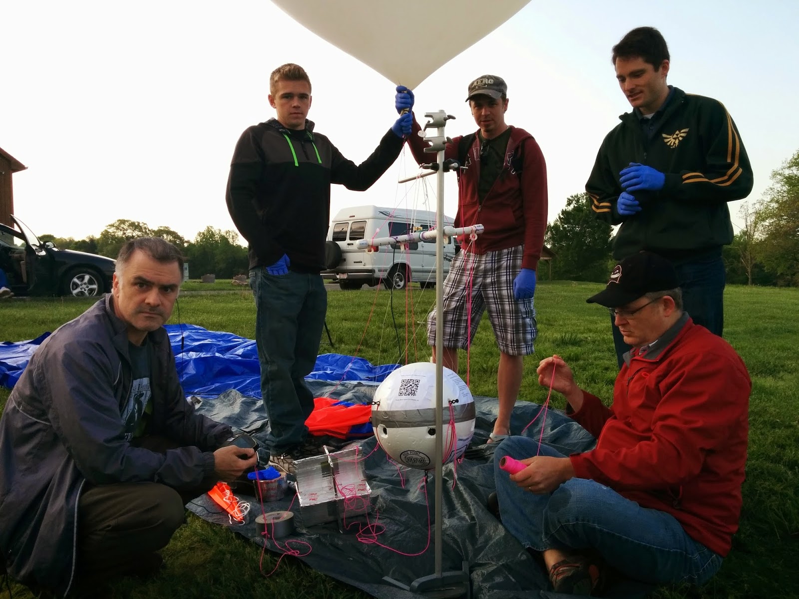
Francois Dion, Rich Graham, Brent Wright, Chris Shepard and Jeff Clouse
Carabiner clipped to my belt while Jeff adds redundant safety strings
Francois Dion
@f_dion

Friday, January 2, 2015

Innovation is not a hotdog

Once upon a time


You would walk in a supermarket, buy hot dogs and hot dog buns. It was a pretty straightforward process. Sausage pack, check. Buns, check.

Then, someone had the idea of making a bun length sausage. Hmm, ok, except that different brand of "bun length" sausages and buns all have different metrics. But hey, that's ok, it was a valiant effort.

More is more


Some time passed, and somebody thought, "hey, let's make a sausage longer than the bun!". Of course, all readers will be quick to point out that there never was a sausage exactly the length of a bun, they were either slightly shorter, or slightly longer. It was just a "more is more" marketing.

What's next


You are probably expecting a sausage to appear on the market "shorter than the bun!". And the circle will be complete. But, which one is the better design? Which one innovates? Same answer to both question: the original design for sausage, which dates back to at least the 9th century BC. Anything beyond that is in the presentation (the marketing).

Tech innovation


Now, back to technology. Let's take the phone, for example. Clearly, going wireless was an innovation. Going pocketable was an innovation. Touchscreen. Haptics. Innovations. But the same tech, just in a different (bigger and bigger, a.k.a. "more is more" marketing) package, is not innovation (*cough* apple *cough* samsung). In fact, one could say there is a clear regression in that field (phones used to have battery life expressed in weeks, could fit in your pocket, even in jogging shorts, could be dropped multiple times on rock hard surfaces without any problem etc)

You can do it


So, why am I talking about all of that? Well, it's my yearly encouragement to truly innovate (see last years post here). But you can't do it in a vacuum. Engage in your local community. If you haven't done so yet, make it a goal this year. Your local programing user groups (Python, Java, Javascript, whatever), maker space or hacker space, robotics, raspberry pi or other creative group, you local coworking, STEM/STEAM school groups etc. Not only will you benefit from attending, by growing your network and your knowledge, but you'll contribute something back to your community, to the society.

Before I sign off for the day, do read my post on innovation in general and personal scale innovation from last year.

@f_dion

Wednesday, January 1, 2014

2013 Raspberry Pi Python Adventures Review

More work, less social media


2013 kept me quite busy. I worked hard on Dion Research doing digital signage and interfacing with manufacturing equipment. I also took on a new position doing more Python development. And increased quite a bit the number of social events in the local Python community (actual physical events). What this means is that social media interaction slowed down some. This was even worse in the other languages, such as french, spanish and portuguese. The output there was quite spotty. Still, some of the articles and tweets I posted in 2013 were quite popular.

Most Popular


Hardware hacking and Python in the browser were the 2 most popular themes. In fact, in the #1 spot by far in terms of views in 2013 was an article on Brython from December 2012:

http://raspberry-python.blogspot.com/2012/12/brython-browser-python.html

Now, a year later, Brython has been through many changes, including more javascript compatibility (and ongoing restructuring). You can learn more by checking out the Brython documentation.

Soliloquy: I spent a few weeks preparing something on Brython for PyCon, but the talk didn't get accepted, unfortunately, and has left me a bit ambivalent about conferences: Is my time better served building elaborate talks on open source projects I contribute to, for conferences I may not get invited to? Or spending the time on the actual projects coding, or even on this blog?

But not all is a loss for you, the reader, since I'll post some of that material on this blog in the coming months.

The #2 was this article on making your own GPIO cable for the still very popular Raspberry Pi:

http://raspberry-python.blogspot.com/2013/02/making-your-own-raspberrypi-gpio-cable.html


Completing the podium at #3 for 2013 was:

http://raspberry-python.blogspot.com/2013/01/pyhacking-step-by-step.html

Least Popular


The least popular articles were all administrative in nature, such as the announcement of the addition of a contact form. It is clear that very few are interested in these kinds of posts, and they will continue to stay at a minimum for 2014.

2014

I just started yesterday a PTOT[D, W, M] (Python Tip Of The Day, Week, Month...). I'm curious to see how popular that will turn out to be. I'll also be introducing something new to help Windows users to get the most out of Python. Still, I recommend to get yourself a Raspberry Pi running Linux as a sidekick to your Windows machine, you'll be happier that way.

I'm also thinking about covering web.database, browser.local_storage, sqlalchemy, alembic and a few other database related themes.


What are some of the themes you'd like to hear about?


François
@f_dion

Friday, February 1, 2013

Making your own RaspberryPi GPIO cable

Example of a DIY circuit, connected by DIY cable

One feature that has contributed to the Raspberry Pi's success is the possibility of interfacing the virtual (software) with the physical world. We are speaking of course of the "General Purpose Input and Output" pins, more commonly known as GPIO. They are available on the Pi at the P1 connector.

Making a GPIO cable


We are doing some green computing today! We are going to recycle some old computer cable and make a Raspberry Pi interface cable with it. We will then be able to connect motors, LEDs, buttons and other physical components.

The interface cable is a flat cable with 26 conductors. It is quite similar to an IDE hard disk cable (or ATA) with 40 conductors (avoid the ATA66/133 with 80 conductors):

Original IDE/ATA cable with 40 wires

Let's get to work


We will only need 2 connectors on our interface cable and not 3. With a cable with 3 connectors, we just need to cut one section off.

Cutting it with a pair of scissors

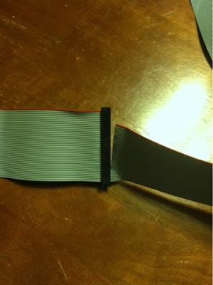
Before doing the cutting, we will do some marking. The reason is that we only need 26 wires, and we have 40. With the red wire on the left, we have to count 26 wires and mark the split with a fine permanent marker. We count on the right side to make sure we do have 14 conductors, not a single one more or less.


Using a permanent marker to write
We are going to divide the cable in two parts, using an x-acto style knife or scalpel: one with 26 wires and one with 14 wires.

splitting in two parts

We then have to cut one section of the connectors off, with a small saw, such as a metal saw (or a Dremel style cutting wheel).

we need to cut on the 7th column from the right

We remove the top part, then the cable section with 14 wires, and finally, after notching it, we remove the bottom part.

almost done, just remove the part on the right

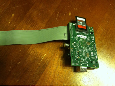
We are done with the cutting. We can now connect the cable to the Raspberry Pi. The red wire is closest to the SD card side, and farthest from the RCA video out (yellow connector):


Connections


With the cable ready, we are now going to test it. Let's add 2 LEDs to do this test. We will use a red and a green LED, but you can use amber or yellow LEDs too. Blue, violet or white LEDs will not work, since they need more voltage.

The connection is really simple:

Red LED and green LED, short leg -> third hole on the left.
Red LED, long leg -> second hole on the right
Green LED, long leg -> third hole on the right


Python Code

First thing first, you have to get the  RPi.GPIO  Python module.  It is a module that will allow us to control the GPIO of the Raspberry Pi. On Raspbian, it is now included, but for another version of Linux, it can be installed with

sudo easy_install RPi.GPIO

Or through apt-get  (or equivalent package manager):
 
$ sudo apt-get install python-rpi.gpio
 
Here is the code:
 
#!/usr/bin/env python  
""" Setting up two pins for output """  
import RPi.GPIO as gpio  
import time  
PINR = 0  # this should be 2 on a V2 RPi  
PING = 1  # this should be 3 on a V2 RPi  
gpio.setmode(gpio.BCM)  # broadcom mode  
gpio.setup(PINR, gpio.OUT)  # set up red LED pin to OUTput  
gpio.setup(PING, gpio.OUT)  # set up green LED pin to OUTput 
#Make the two LED flash on and off forever  
try:
    while True:  
        gpio.output(PINR, gpio.HIGH)  
        gpio.output(PING, gpio.LOW)   
        time.sleep(1)  
        gpio.output(PINR, gpio.LOW)  
        gpio.output(PING, gpio.HIGH)  
        time.sleep(1)
except KeyboardInterrupt:
    gpio.cleanup()

Just save the code into a file named flashled.py.

  • PINR is the GPIO for the red LED (0 for Rpi V1 and 2 for V2)
  • PING is the GPIO for the green LED (1 for Rpi V1 and 3 for V2)
We select the Broadcom mode (BCM), and we activate the 2 GPIO as output (OUT). The loop will alternate between the red LED on / green LED off during 1 second, and red LED off / green LED on during one second ( time.sleep(1) ). By doing a CTRL-C during execution, the program will terminate after cleaning up after itself, through the gpio.cleanup() call.

Running the code


Usually, a LED should be protected with a resistor to limit the current going through it, but in this case it will blink intermittently, just to test the cable, so we don't need any.

For continuous use, it is recommended to put a resistor in series (about 220 Ohm to 360 Ohm).

Before we can run the program, we have to make it executable:
$ chmod +x flashled.py
$ sudo ./flashled.py
CTRL-C will stop the program.

Red LED

Green LED
This concludes our article. I hope it was satisfying making this cable and recycling at the same time.

The follow up to this will be about making our own breadboard adapter, and having fun with a transistor.


@f_dion

Nouvelle publication DIY

faitmain

Un nouveau magazine vient de paraitre, il s'agit de Fait Main, un magazine collaboratif en ligne et en PDF:

http://www.faitmain.org

On y retrouve divers sujets autour du DIY("Do It Yourself"), et dans ce premier numéro, on y parle bien sur de Raspberry Pi.

J'ai écris l'article "câble d'interface pour Raspberry Pi" Lire l'article 

Mais ce n'est pas tout: 

Contenu du volume 1

La tribune de ce numéro est un parallèle entre web hébergé et OGM. Lire la tribune 

Le premier article présente une application de reconnaissance de feuille écrite pendant un Hackathon. C'est l'application qui a été écrite en 24 heures par Olivier, Ronan & Tarek lors du dernier AngelHack à Paris. On y parle de machine-learning au service des plantes, des hackathons de programmation & de responsive design . Lire l'article

Le deuxième article parle de domotique et vous explique comment piloter des dispositifs sans fils - portails, détecteurs de mouvements etc. On y parle d' Arduino , de Raspberry-PI et de signal en 433 mhz . Lire l'article 
 
Le troisième article présente le travail de Marcin Ignac: des méduses animées en 3D. Des captures d'écran de ces méduses ont ensuite été utilisées pour faire partie d'un projet de livre génératif. On y parle d' animation procédurale , de processing.js & d'hachurage. Lire l'article

Le quatrième article vous donne 5 conseils de photos culinaires pour que vous puissiez prendre en photos vos soupes, gigots et autres desserts comme un(e) pro. Lire l'article 

Suit une interview de Hugues Aubin au LabFab de Rennes. Lire l'article .

Un cinquième article sur la conception d'un Juke box avec un Raspberry-PI, sans aucune soudure requise :) Lire l'article 

Le sixième article vous explique comment recycler une vieille nappe de disque dur pour connecter le GPIO de votre Raspberry. Lire l'article 

Le septième article est une rapide présentation du jeu The Midst , conçu avec Processing et WebPD. Lire l'article 

Enfin, le huitième article aborde les bases du fonctionnement d'une CNC. Lire l'article 
Bonne Lecture!
— Tarek

Equipe

Le projet FaitMain est monté par Tarek Ziadé mais est surtout possible grâce aux créateurs d'articles et aux relecteurs.

Ont participé à ce numéro :

New DIY publication

faitmain


It is a collaborative magazine that is both online and in PDF format. It was just launched this morning. It is in french.

faitmain.org

 So why am I talking about it in english?

Because one of the article from the publication will be available on my blog, a little later. This is just a heads up.

How to make your own cable


The Raspberry Pi has a connector with a bunch of pins, and it is taunting you!  Make good use of it by recycling an old IDE hard disk cable. The article will also show you how to test it with some Python code.

The article in French on faitmain.org:  faire un cable gpio

The article in Portuguese on this blog: fazer um cabo gpio

I'll update this post when the English version is available, and add it also to the tutorial section

[UPDATE] The article in english: making a gpio cable


@f_dion