Showing posts with label hardware. Show all posts

Saturday, June 3, 2017

Readings in Technology

"Ex-Libris" part III


I've made available part 3 of my "ex-libris" of a Data Scientist. This one is on Technology, from some historical perspective (ie. Turing, Shannon, Von Neuman) all the way to the most recent trends (ie. Ansible, Docker, Cloud, Continuous Integration, Performance etc) and can be found on LinkedIn:

"ex-libris" of a Data Scientist - Part III

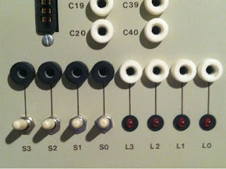
My CES Industries EdLab model #804, in the History section


See also


Part I was on "data and databases": "ex-libris" of a Data Scientist - Part i

Part II, was on "models": "ex-libris" of a Data Scientist - Part II

Part IV is right around the corner, and will have a significant Python section.


Francois Dion
@f_dion

Friday, June 2, 2017

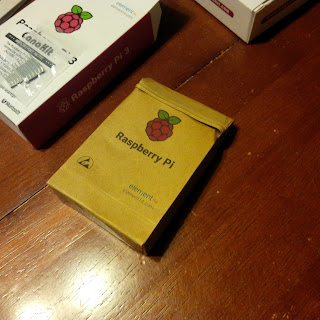
Raspberry Pi 3 Canakit

It's been a long time...


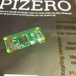
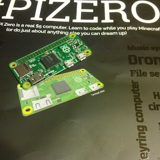
I don't even remember when was the last time I talked about Raspberry Pi hardware on my blog. I do remember the first time, however, some 5 years ago. Meanwhile, the price of Raspberry Pis have both gone down (Zero) and up (Raspberry Pi 3) due to economies of scale, Moore's law and removal / addition of components from the various versions.

Raspberry Pi 3


So, I realize that I've covered everything from the original Raspberry Pi model B with 256MB of ram, all the way to the Raspberry Pi 2 and Zero, but nothing on the Raspberry Pi 3. I typically don't buy kits, but I picked one up to see how that would work for people who had never used a Raspberry Pi before. The reason there is that I suggested to my fellow data scientists (and those interested by data science, and whoever else who reads my posts) to also be technologists, to get better acquainted with technology and hardware. And to get one (or four - I'll follow up on that) Raspberry Pi 3. I wanted to make sure it would be smooth sailing.

The Canakit


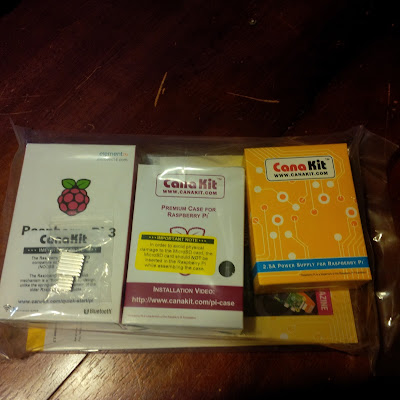
I ordered a Canakit with a Raspberry Pi board and two heatsinks, a case, a 2.5A power supply and a guide. It is convenient to get a single ready to go package quickly, particularly with free 2nd day shipping (you know who).

I say ready to go, but not quite. Of course you'll need a monitor, keyboard and mouse if you don't enable ssh (distro dependent ways, some have ssh enabled by default). But you'll also need an SD card.

No SD card?


The kit I ordered basically got you the case, heatsinks and power supply for $15 above the price of the Raspberry Pi 3. But no microSD card. The step above kit includes a microSD card with the OS already pre-installed, but when I looked at it, the price difference was too much for just that and a plain HDMI cable.

Oh, but it's so hard to prepare an SD card! Don't panic. Use Etcher. Later, when you get your command line skills up, you'll be able to do it with dd.

If you get stuck, leave a comment or contact me on twitter

Francois Dion
@f_dion

Thursday, October 6, 2016

Improving your communications: Professional Audio-Video Production on Linux

Pro AV on Linux

I'll be presenting on the subject of Professional Audio-Video Production on Linux, next week at TriLug.


From concept to finished product, it has never been easier to obtain professional results when it comes to audio-video production on Linux.

We will cover some of the hardware that should be part of your production suite, from microphones to jog wheels and highlight some of the top tools for animation, audio, broadcasting, effects, modeling, music, transcoding and video. We will also go beyond the usual suspects and introduce some tools that might not be typically used for AV production.
By the end of the presentation, you will have all the tools you need to improve the quality of your communications, for your personal enjoyment, your career, or your business.

When

Thursday, 13 October 2016 - 7:00pm to 9:00pm
Where
The Frontier, 800 Park Offices Drive, Durham, NC
Francois Dion
@f_dion

Sunday, September 18, 2016

Something for your mind: Polymath Podcast launched


Some episodes
will have more Art content, some will have more Business content, some will have more Science content, and some will be a nice blend of different things. But for sure, the show will live up to its name and provide you with “something for your mind”. It might raise more questions than it answers, and that is fine too.

Episode 000
Listen to Something for your mind on http://Artchiv.es

Francois Dion
@f_dion

Sunday, August 9, 2015

Computing at 80,000ft, future tech and the future of tech


Another exciting Winston-Salem Section meeting at CDI !  Wednesday, August 12, 2015 at 11:30am.

Presenter: Francois Dion

Originally from Montreal, Canada, Francois Dion is a Coder, Data Scientist, Entrepreneur, Hacker, Mentor, Musician, Polyglot, Photographer, Polymath and Sound Engineer.  He is the founder of Dion Research LLC, an R&D firm specializing in Fully Integrated Software and Hardware (www.dionresearch.com) and works as a Data Scientist at Inmar, Inc. (www.inmar.com).

He is also the founder of the local Python user group (PYPTUG), a group he founded to “promote and advance computing, electronics and science in general in North Carolina using the Python programming language.”

Detail:

Behind the scene and various aspects of electronics and computing cluster and data science in near space. A glimpse at future technology. and at the future of technology.

When
Date: 12-August-2015
Time: 11:30AM to 01:30PM (2.00 hours)
All times are: America/New_York
Where

Building: CDI
Center For Design Innovation
450 Design Ave.
Winston Salem, North Carolina
United States 27102
Staticmap?size=800x400&sensor=false&zoom=16&markers=36.0906389%2c-80
More

No Admission Charge.


Thursday, April 30, 2015

The computer network in space - Part 2


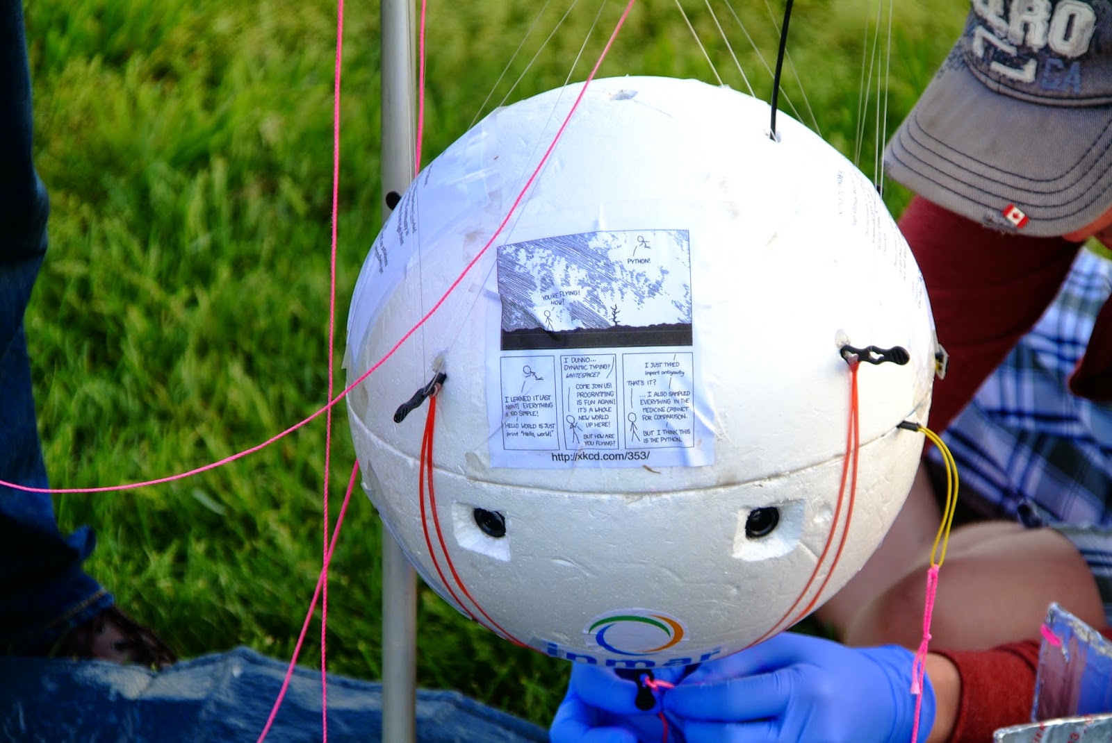
- You're flying! How?
- Python!
( https://xkcd.com/353/ )

Continued


Part one of this series of articles on Team Near Space Circus flight NSC-01 can be found  >here<. It covered the physical layout of the 7 Raspberry Pis, 8 cameras and power system. It left off as we were about to go into the details of the network topology itself.

A satellite or a bowl of spaghetti?

Plan A: 2 Pi in a Pod...


The initial plan was for 2 Raspberry Pi using a serial communication protocol. The Model A+ does not have an ethernet port. Of course a Raspberry Pi 2 has one, and is more powerful, but it also consumes a lot more power than the A+. Our battery pack would have had to be much larger if we went down that path, and that meant significantly heavier. We had a goal of 2Kg for the payload itself, and we were getting close, so serial it was...

Serial communication


DB25 (serial or parallel)
DB9 (serial)

Many early personal computers typically had two interfaces, either built in or available through an expansion card: a serial (either a DB9 or DB25 connector) and a parallel interface (either a DB25 or 36 pins Centronics connector, aka IEE1824). The parallel interface was typically used for printers (and great for DIY DACs with resistor ladders, but that's a story for another time), while the serial port was mostly used for modems or scientific equipment.

RS-232 was introduced in 1962, so it's been around for quite a while now. Many serial connections were actually TTL (5V), such as on the Digital Decwriter III, but it was quite easy to convert them to a +/- voltage range (and even more so since the mid 80s with ICs such as the MAX232). The initial purpose was to connect a DTE (Data Terminal Equipment), a fancy way of saying a computer, and a DCE (Data Communication or Circuit-terminating Equipment).

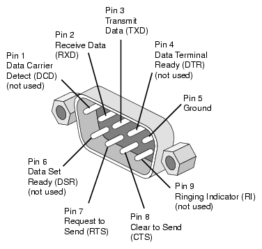
On a DB9 connector, the pins would be (DB9 male connector pictured):

RxD is Receive Data and TxD is Transmit Data. What if you need to connect two DTE together? You need a Null-Modem adapter or cable. The simplest Null-Modem circuit requires 3 wires (2 if you can guarantee the ground on each end to be the same):

GND(7) to GND(7), TxD(5) to RxD(4), RxD(4) to TxD(5)

Raspberry Pi Header


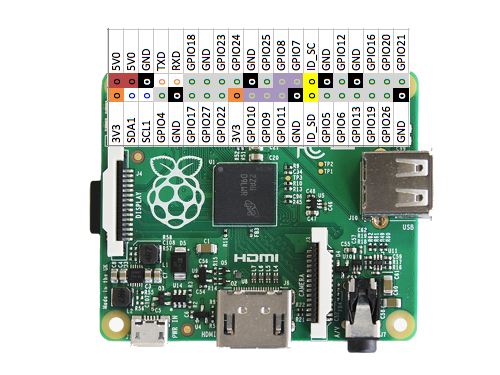
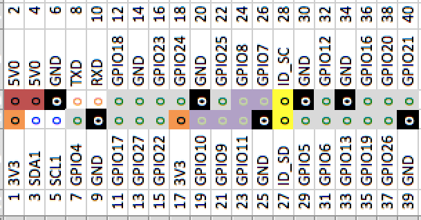
The Raspberry Pi doesn't have a DB9 or DB25 connector. But if you look at the 40 pin header, notice on the top row, the 4th and 5th pins:
Raspberry Pi Model A+ with pinout as overlay

TXD and RXD. It is a serial port, but it is *not* RS-232 compatible as far as voltage levels are concerned (a 1 is marked by a negative voltage in the range -3V to -15V, and a 0 by a positive voltage in the range +3V to +15V), as it is a TTL interface (a 1 is marked by a positive voltage, either 3V3 or 5V and a 0 is marked by 0V). But that is fine, we are only connecting to another Raspberry Pi.

The primary issue with this serial port is that the Raspbian operating system has a console (TTY) associated it. Meaning that you could connect this to a computer, with the right cable, and see the boot process and get a console prompt, and be able to type commands, as if you had a keyboard and monitor connected directly to the Raspberry Pi.

In our case, however, we want to use the port for something else, our own communication network, so we have to disable this feature. It was once a manual process, and I had written a script to do it, but...

Configuration


sudo raspi-config

The raspi-config now has an option under the Advanced Options selection to disable the serial port console, so we can use it directly:

Advanced -> Serial
Once we have reconfigured the serial port, we can quit raspi-config and reboot. For each compute node, beside disabling the serial port console, we also enabled on the advanced page the SPI and I2C options, and on the main page we configured the time zone, enabled the camera and expanded the filesystem. We also overclocked nodes 1-3 to 800 MHz while nodes 4-6 ran at 700 MHz (so we can measure the impact of overclocking).

Plan B: A Pi cluster

By using a pair of Raspberry Pi, the communication process is pretty straightforward. With two nodes, we can use SLIP or Point to Point Protocol (PPP). Initially, this was the thought for NSC-01 and we would not have to write the code for the network layer.

6 Raspberry Pi cameras
1 Infrared Raspberry Pi camera (pointing down)

But without a functioning camera switcher, the only option was to use one node per camera (each Raspberry Pi has 1 CSI camera connector, even thought the Broadcom chip supports 2 - most cell phones have a front and rear camera). With 7 CSI cameras in total, that meant 7 Raspberry Pi.

Time to dig in our bag of tricks...

Token Ring

4 Node token ring network architecture


As I was going through the options, I started thinking about good old IBM Token Ring (and FDDI). Conceptually, at least. I wasn't going to make something compatible with 802.5, but instead reuse the concept with the serial UART, transmit to receive from one node to the next.

Conceptually, a node is always listening to the serial port. Is this data for me? (if it's a broadcast or if it's addressed to me) If not or if a broadcast, I send it right away to the next node, and process it if it is addressed to me. So let's get into the details.

The diagram


7 Raspberry Pi networked together
In the previous article, one of the pictures clearly showed 7 Raspberry Pi connected together inside the payload. I've included here a fritzing diagram to help in detailing what is going on here.

In the diagram above, I didn't have a Raspberry Pi model A+ for fritzing, so I used the closest thing for our purpose, a Raspberry Pi model B+. Both of them have a 40 pins GPIO header. First row at the top, from left to right has 5V, 5V, GND, TxD and RxD. We'll stop there for right now.

Here I've simply connected node 1 TxD to node 2 RxD (blue wire), node 2 TxD to node 3 RxD (pink), node 3 TxD to node 4 RxD (brown), node 4 TxD to node 5 RxD (cyan), node 5 TxD to node 6 RxD (orange), node 6 TxD to node 7 RxD (yellow) and finally node 7 TxD to node 1 RxD (green), in a nice circular (or ring) fashion.

The GND are not daisy chained from one Pi to the next, because they are all powered by the same source, through their microusb plugs.

Initially, I tried to power the Pi directly from the 5V pin on the GPIO header, but the signal was decoding only partly. By further connecting the 3.3V (that was key, the UART operates at 3V3 so the HIGH signal was not detected reliably when powered with only 5V) and GND together, it made it more reliable, but also more complicated. I reverted back to powering all the 7 nodes using microusb (as detailed in the previous article).

Python


What's great about Raspbian is that not only do we have Python installed, but Python 2.x and 3.x are there, along with many things that are normally optional, such as pygame, pyserial, RPi.GPIO etc. Batteries are quite definitely included with Python on the Raspberry Pi.

Still, for the networking software, we did install two modules from pypi using pip3 (we are using Python 3), docopt and sh.

For the bulk of the development, I used a Raspberry Pi Model B+ connected to my laptop and to a second Raspberry Pi using the serial port and the network switch. That way my laptop could see both Raspberry Pi and I could push new versions of the software using scp.

I also had a "field" version, in case I needed to do last minute changes:

Raspberry Pi sidekick in sidecar configuration (DHCP server on laptop)

Docopt


docopt: helps you to define interface for your command-line app, and automatically generate a parser for it.

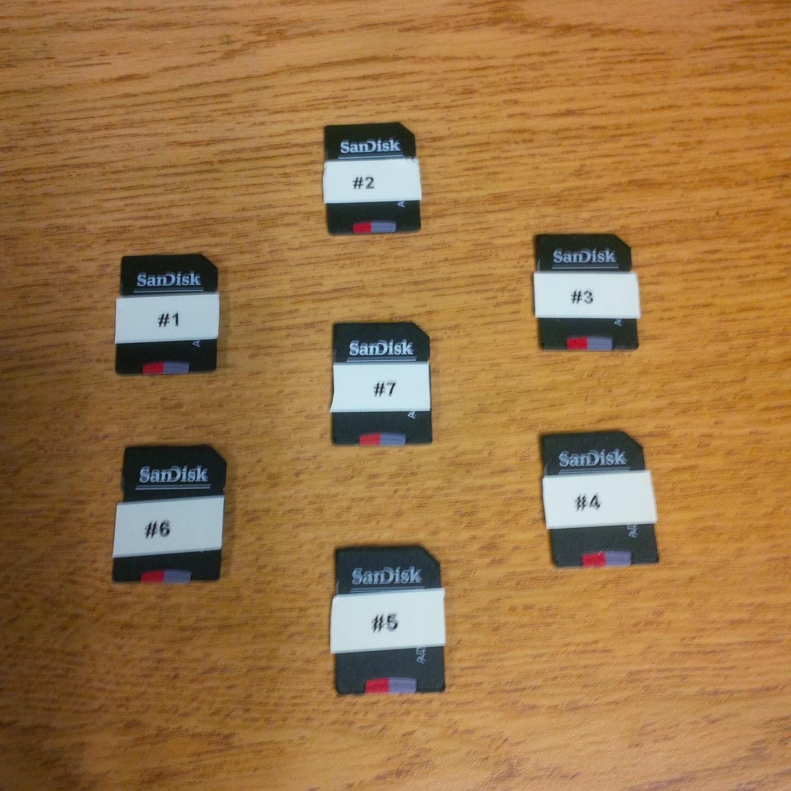
For example, in the case of the network controller, token.py, it accepted one argument, the node number. In the future, we'll probably derive the node number from a personality module on the GPIO header, but it was a simple solution that could be done in software, not adding any weight to the payload. The downside was having to keep track of all the microsd cards:
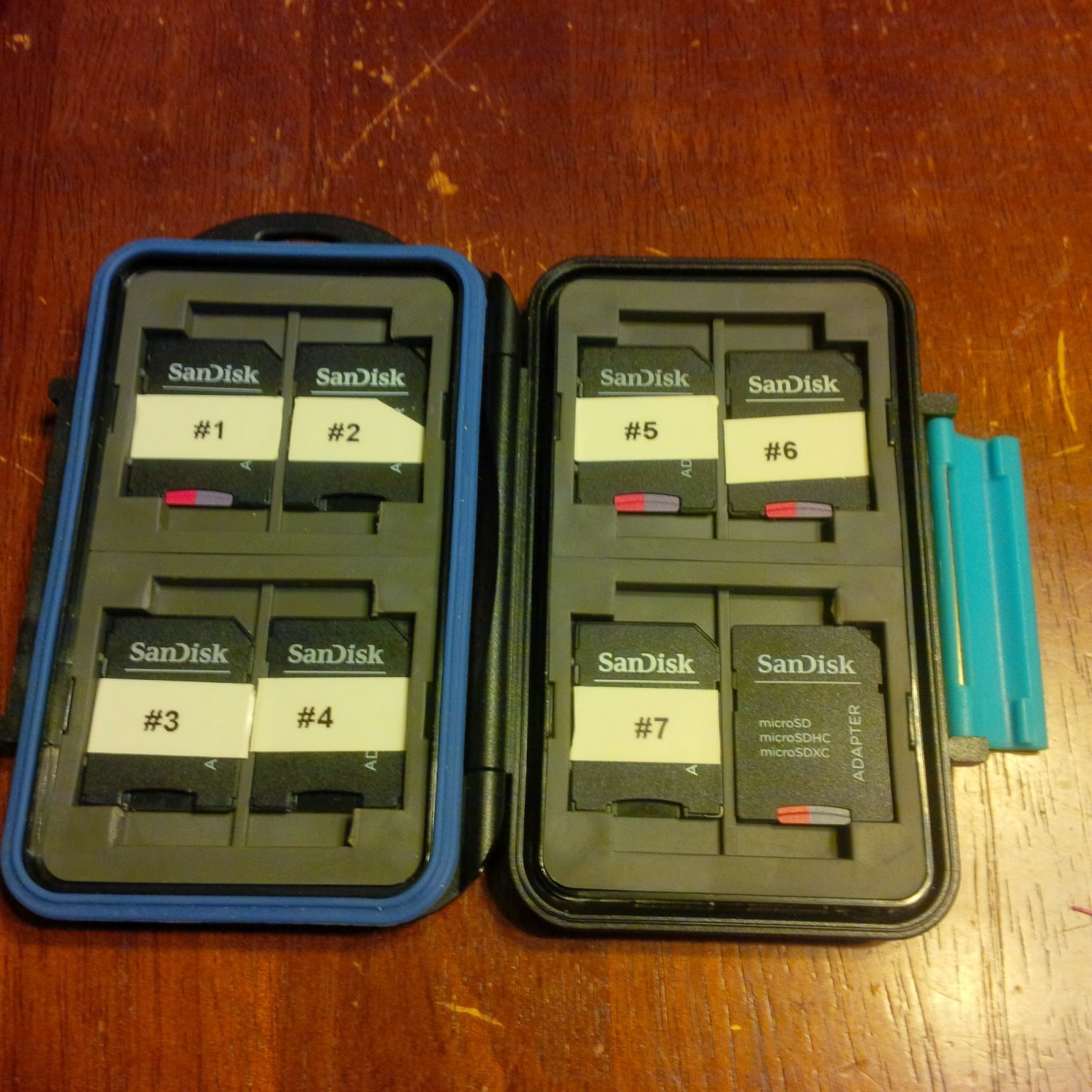
micro SD card transport - For nodes 1 to 7 plus 1 backup


And, so back to docopt, here is how it was used for token.py. At the top of the file, after the shebang line (so the script can be an executable), I included the docstring which defines the interface (lines 2 to 5), which is a required field <address>. This is a simple case, but as cases get more complicated, it really pays off to use docopt.

Then on line 14 I import the docopt module (I group imports alphabetically first by what's included, then a blank line, then again alphabetically I add the imports that have to be installed - just a convention):

1 :  #!/usr/bin/env python3  
2 :  """  
3 :    
4 :  Usage: token.py <address>  
5 :  """  
6 :  from datetime import datetime  
7 :  import logging  
8 :  from logging.handlers import SysLogHandler  
9 :  import RPi.GPIO as gpio  
10:  import serial  
11:  import subprocess  
12:  from time import sleep, time  
13:    
14:  from docopt import docopt  


I then conclude the script by passing the arguments that docopt figured out are there (and validated) in the docstring (__doc__), to the main function:

168:  if __name__ == "__main__":  
169:    arguments = docopt(__doc__)  
170:    main(arguments)  
171:    


And how does one use it in the code itself? In the body of the main function I do the following:

97 :    
98 :  def main(args):  
99 :      my_addr = int(args['<address>'])  
100:


In case an air traveler wants to check our website...

SH

sh: is a full-fledged subprocess replacement for Python 2.6 - 3.4 that allows you to call any program as if it were a function:

`python from sh import ifconfig print ifconfig("eth0") `

Continuing with the code in token.py, you simply import what you need from the shell and sh transparently builds a function for you to call. In this case I needed access to date and rmmod:

1:  #!/usr/bin/env python3  
2:  """  
3:    
4:  Usage: token.py <address>  
5:  """  
6:  from datetime import datetime  
7:  import logging  
8:  from logging.handlers import SysLogHandler  
9:  import RPi.GPIO as gpio  
10:  import serial  
11:  import subprocess  
12:  from time import sleep, time  
13:    
14:  from docopt import docopt  
15:  from sh import date, rmmod  


Then further down in the code I can call date() to call the actual date command from the OS so it is not only in the right format, but in the right timezone (there are other ways to do this, but sh was going to be used heavily for gathering stats, so it made sense to introduce it here):

154:      # synchronize time  
155:      s = str(date())+' \n' # from the OS  
156:      bin = bytes(s, "ascii")  


Pyserial


So, how about accessing a serial port in Python? And are there things to keep in mind when using Python 3?

First thing first, we import serial (line 10). This module is already installed on the Raspberry Pi.

Then, within the body of the main function, we establish a serial connection (line 101). We specify the device that corresponds to the serial UART. This is /dev/ttyAMA0. We also specify the bitrate, expressed in bits per seconds (bps). 115200 is the fastest we can use with the default clock settings for the UART, and is what was used for the flight. As a reference, acoustic coupler modems worked at 300 bps...

We felt that at higher rates it might not give us as reliable a signal, but we will experience with faster rates on future flights (we only had time to do 1 flight within the Global Space Balloon Challenge window). Back in 2012, Gert Van Loo stated:

"The UART and the SPI can be driven by DMA so there is no SW limitation.The real maximum for all those interfaces is only set by the signal integrity.This is certainly the case for I2C as it has to use pull-up resistors to get the signals high again.I know the clocking is rather confused. I built the damn chip and I still have no idea how to control all the clocks.The clocking structure is very complex with a limited number of resources (PLL's) which are used for aplethora of things to drive. (A quick count shows 36! clocks being generated) There will be many cases where it is just not possible to give you ALL the frequencies you want."
And in fact, it is possible to get up to 921600 bps (8 times what we used) in a controlled environment, at the OS level In an environment full of RF, including a 10W 2M transmitter, with a python module, I'd be happy with 4 times (460800) or even twice (230400) our rate. If nothing else, it would drive our latency down some.

Wow, that was quite the detour, anyway, back to our establishing the serial connection. The last thing we specify  on line 101 is timeout=1. This is a 1 second timeout. We will be blocking on reads (line 113), but don't want to wait more than 1 second for the data. 

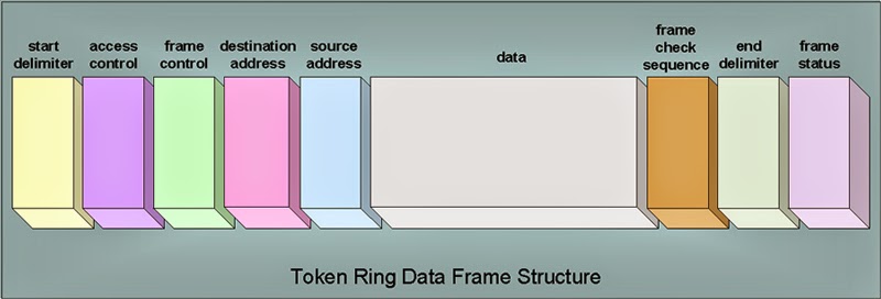
In the original token ring world, a frame is defined in the following way:


A start delimiter, access control, frame control, destination address and source address, then the data, and finally a frame check sequence, end delimiter and frame status. I found this later, after I designed the frame for our system, and it is interesting that it is quite similar, in functionality, but implemented slightly differently.

In our case, the frames are small in size, they should never go above 1 second to transmit. And if they do, then we kick out that partial request and the balance of the request and we'll get the next one that is complete. So, we assume that if we get a full frame, the first byte is always first, and the frame always conclude with a newline (that way the ser.readline() returns before the 1 second timeout). We thus avoid the start delimiter (the end delimiter is newline). 


The first byte for our protocol is the source address (1 byte = 254 addresses, 0 and 255 have special meaning). The second byte is the destination. On an 8 node setting (the default), this is a bitmask, and 255 (FF) is broadcast. On a "large" cluster,  this address is the individual node address, and 255 (FF) is still broadcast. You gain number of nodes, but loose directed broadcast (say, I want to send something to node 1, 2 and 6, I would use a destination of 9 in the 8 node mode, but in extended mode I have to send 3 individual frames). Then the status. This can be a static status (the packet gets back to the originator) or a counter status (each time a node processes the frame, it decreases the status) or a no status needed, where the nodes simple forward the original frame, but do not send a status. This is followed by a command. This allows for shorter data segments, since we just need the variable part of the command. Finally, the data, a variable number of bytes terminated by newline (\n).

As we get to higher speeds, I will definitely add the frame check sequence of the original token ring to our design.

10 :  import serial  
11 :  import subprocess  
12 :  from time import sleep, time  
13 :    
14 :  from docopt import docopt  
15 :  from sh import date, rmmod  
[...]
97:    
98 :  def main(args):  
99 :    my_addr = int(args['<address>'])  
100:    
101:    ser = serial.Serial('/dev/ttyAMA0', 115200, timeout=1)  
[...]
111:    while not master:  
112:      logger.debug("I am SLAVE") # Everywhere but node 1  
113:      tokens = ser.readline()
114:
115:      if len(tokens) == 0:  
116:        logger.debug("No token received in the past 1 second")


What about writes? As an example, in the case of the master controller, it starts its job by sending a KEEPALIVE frame. This is defined by a series of bytes on line 36. Source is 01 (master node), destination is 255 (FF) broadcast, status is FF (no response needed), then command 05 which is a keepalive. Data segment is of length 0 since \n is encountered immediately. This is the shortest well formed frame that can be sent. And that is what the master controller sends on line 152 using ser.write. As long as we keep everything as type bytes, the serial module works well in Python 3.

Pretty simple, overall (!). Well, considering this was all designed over the course of a handful of days. Python really helped.

[...]
36:  KEEPALIVE = b'\x01\xff\xff\x05\n' # keepalive packet  
[...]
149:    # I am master, or I am taking over   
150:    if my_addr == 1:  
151:      sleep(15)  
152:      ser.write(KEEPALIVE)  
153:      sleep(1)  

We will be creating a module for reuse out of the token.py application, so that other people can use a serial token ring setup themselves. This should be published to pypi. We'll also publish a demo implementation for a master/slave setup.

Deadman's Switch

I'm concluding this article here, as it is already quite long. But I invite you to read about a most interesting device, the Deadman's switch. This was used in our High Altitude Balloon, but it can be used in all kinds of scenarios. Read about it here: http://raspberry-python.blogspot.com/2015/04/deadmans-switch.html

And don't forget to check back regularly for more updates, such as part 3 of this series of articles (the data gathering aspects).

Francois Dion
@f_dion
Deadman's Switch

From Wikipedia:
"A dead man's switch (for other names, see alternative names) is a switch that is automatically operated if the human operator becomes incapacitated, such as through death, loss of consciousness or being bodily removed from control. Originally applied to switches on a vehicle or machine, it has since come to be used to describe other intangible uses like in computer software."

NSC-01

For Team Near Space Circus' participation in the Global Space Balloon Challenge with NSC-01, we wanted to make sure that once powered up, and enclosed, we would still have control of the computer cluster and the timeline of events, as to what would happen when. As we devised a network with 7 nodes (see part 1 and also part 2 of the computer network in near space) with a master controller and many slave nodes, we needed a way for the system to wait on a signal from us.

A plain old switch would do the trick of course. But what if the balloon took off and we forgot to flip the switch? Or somebody tripped and let the balloon go? 

Martin DeWitt demoes why we need a deadman's switch

Then the master controller would have stayed in standby mode, sending keep alive frames to the other nodes and we would have had no images, no video, no gps data etc. Not good.


Tethered switch

If you've ever spent any time on a threadmill, no doubt you've encountered a tethered switch. Usually it's a magnetic plug, with a string, terminated by a clip. You clip it to yourself, so if you ever fall down/off the threadmill, you end up yanking the plug off the machine, and it stops right away.

Simple deadman's switch, just needing a string

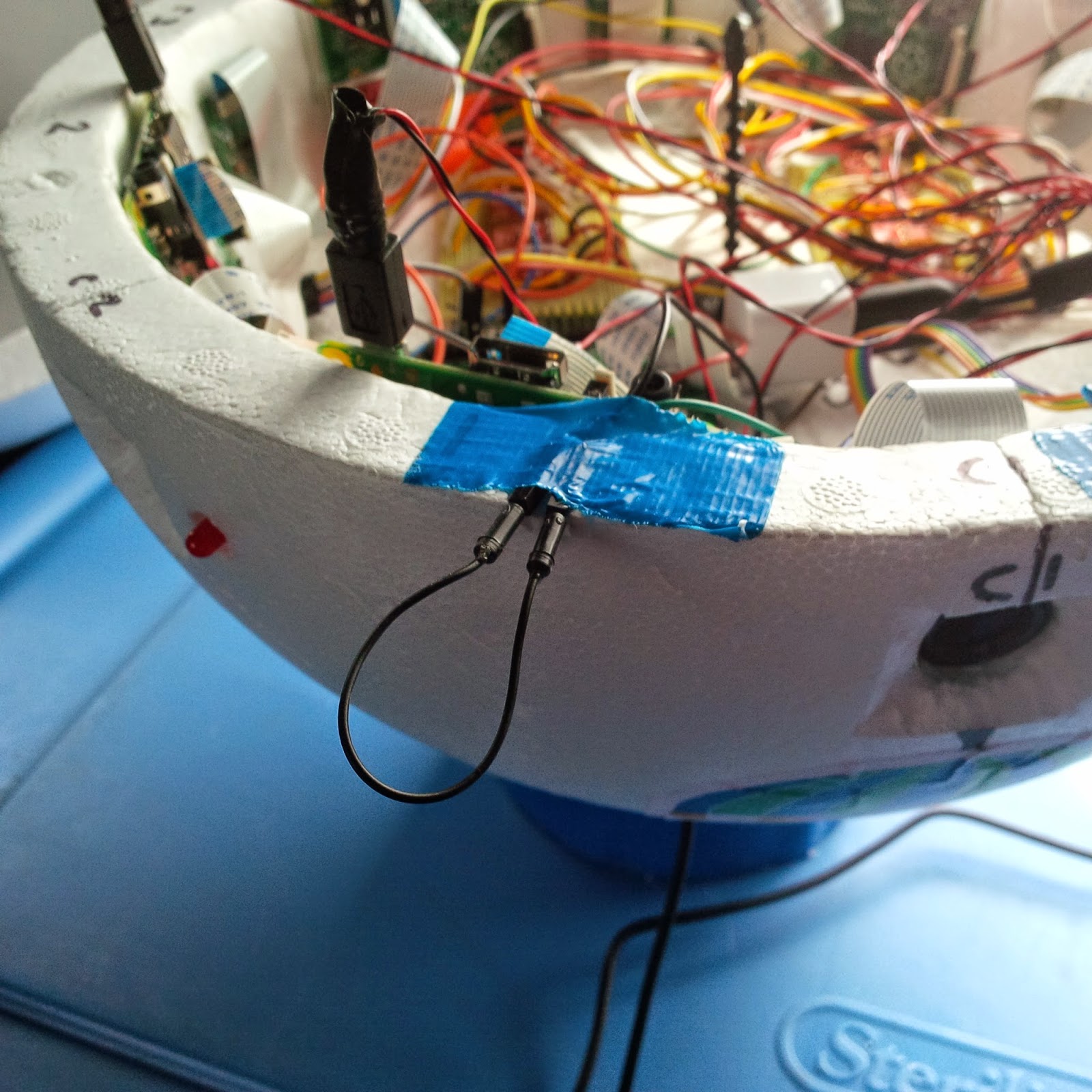
Since the Raspberry Pi has many GPIO pins, all we needed to do was create a simple circuit between two of them that, once interrupted, would signal that it was time for the master controller to go to work.

We will need two GPIO pins, how about GPIO17 and 27?
Why two GPIOS? We could have connected a GPIO to 3V3 and GND through resistors (to protect/limit current), to ensure LOW and HIGH modes. But, trying to keep things as simple as possible from a hardware perspective (software doesn't weigh anything, hardware does), using two GPIOs made a lot of sense. Set one GPIO as input, one as output, raise the output HIGH, the input now sees a value of 1. Open the circuit (by pulling the wire out), and the input no longer sees HIGH, it now reads 0.

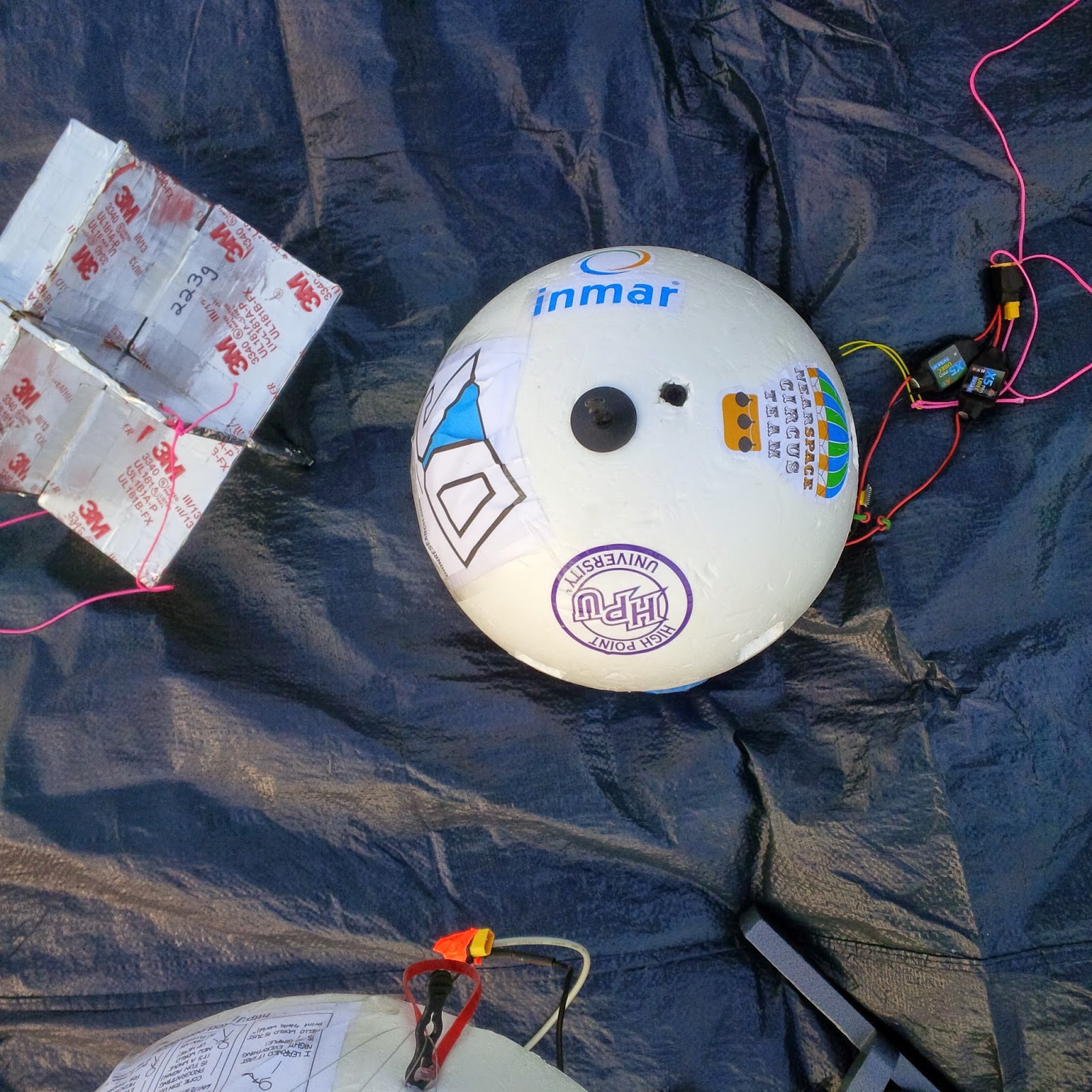
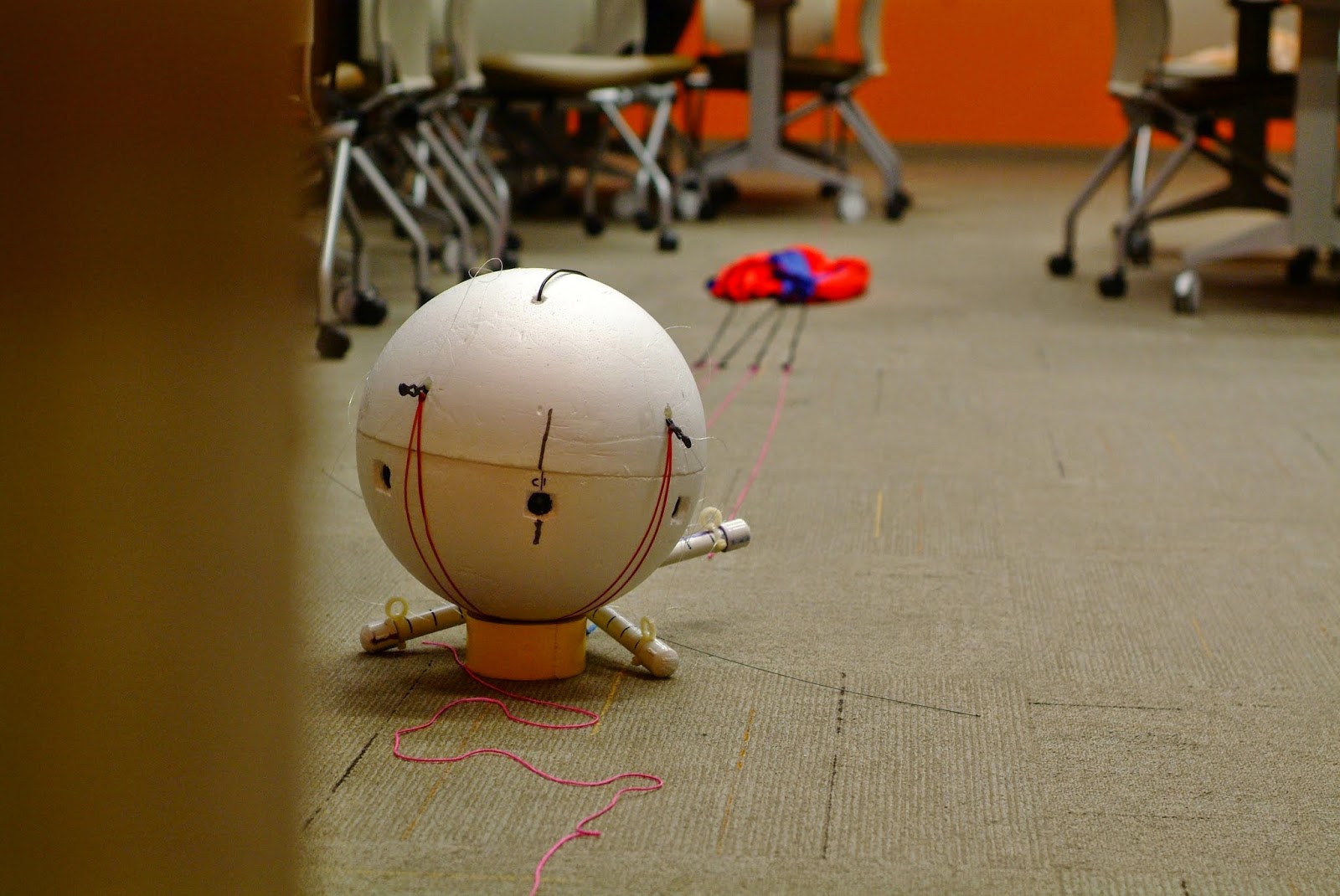
Our sponsors (bottom half of payload) with IR cam
radar reflector on the left, deadman's switch on right w/carabiner

A string attached on one end to the wire sticking out of the side of the payload and on the other end to a carabiner clip is really all that was needed.

Deadman's switch code


We've already covered the serial port, sh and docopt in part 2 of the computer network in near space. If you are wondering about these things (and lines 98 to 101 in the code below) I urge you to go and read that article first. I've left here the core of what is needed for implementing the software side of the deadman's switch. We first need the GPIO module. On line 9, we import it as gpio (because uppercase is usually reserved for constants). Then on line 102 we set up the gpio module to operate in BOARD mode. That means physical board pin numbers. In the field, you can always count pins, but you might not have a GPIO map handy... But if you prefer Broadcom nomenclature there is a mode for that too.


So GPIO17 is the 6th pin on the bottom and GPIO27 is the 7th. Since odd pins are at the bottom and even at the top, this means pin 11 and 13. Line 103 sets up pin 11 to be an output, and line 104 sets up pin 13 to be an input. Finally, line 105 "arms" the deadman's switch by setting pin 11 to HIGH. Pin 13 should now be reading a 1 instead of a 0.

9:  import RPi.GPIO as gpio 
[...]
98:  def main(args):  
99:    my_addr = int(args['<address>'])  
100:    
101:    ser = serial.Serial('/dev/ttyAMA0', 115200, timeout=1)  
102:    gpio.setmode(gpio.BOARD)  
103:    gpio.setup(11, gpio.OUT)  
104:    gpio.setup(13, gpio.IN)  
105:    gpio.output(11, gpio.HIGH)  


We are now going into the actual functionality of the switch. We establish a simple while loop on line 161, reading pin 13. As long as we see 1, the circuit is closed and on line 162 we send a KEEPALIVE frame to the other nodes (see previous article). We also sleep for 1 second on line 163 (no need to poll faster than that). The moment we get a 0, the while loop exits, and before starting the master controller on line 165, we log our launch time on line 164 (the logging aspects will be in a future article).


[...]
159:    
160:    # deadman's switch  
161:    while gpio.input(13) == 1:  
162:      ser.write(KEEPALIVE)  
163:      sleep(1)  
164:    logger.debug("We are launching! (on {})".format(datetime.now()))  
165:    master_controller(ser, counter) # forever controlling the Pi network until I die    


And that is it!

This can be implemented in all kinds of different projects. Have fun with it!

Francois Dion, Rich Graham, Brent Wright, Chris Shepard and Jeff Clouse
Carabiner clipped to my belt while Jeff adds redundant safety strings
Francois Dion
@f_dion

Monday, April 27, 2015

Excellent mission debrief tonight

Pictures brought back by NSC01


In the coming days and weeks we'll publish charts and graphs, and we'll be working on images and videos. For right now though, I don't really feel like typing much, so I'll leave you with a few pictures... (Captured using a webcam and pygame and an infrared Raspberry Pi camera, all from node #7 of the compute cluster)

Infrared image, lakes are easy to see on those (and our radar reflector)

About to be launching

Official launch image, April 21st 7:57:24
Francois Dion
@f_dion

Friday, April 17, 2015

The computer network in space - Part 1!

First in flight


First in flight is the (unofficial - official is "Esse quam videri") North Carolina motto.

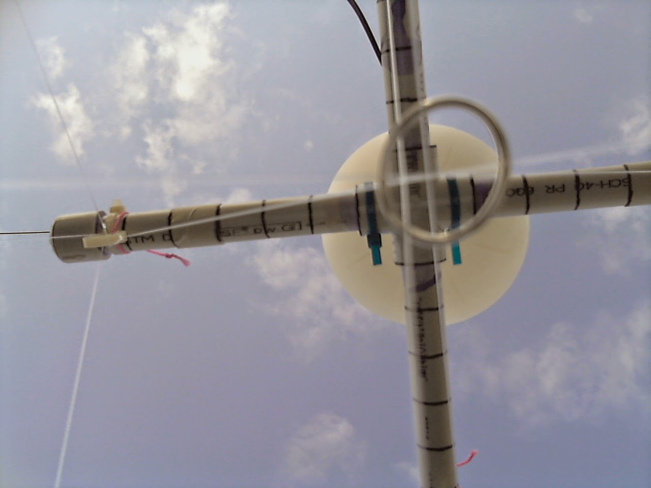
Our launch is not a first in flight from a HAB (high altitude balloon) perspective (see also: "Rocket man and the Near Space Circus"), but the mechanical aspects (see also the article on our self-leveling rigging: "learn from the past - 103 years old technology in space"), hardware and network topology and innovations packed in the software will definitely be first in flight.(Launch is now D-1, April 21st from Mocksville)

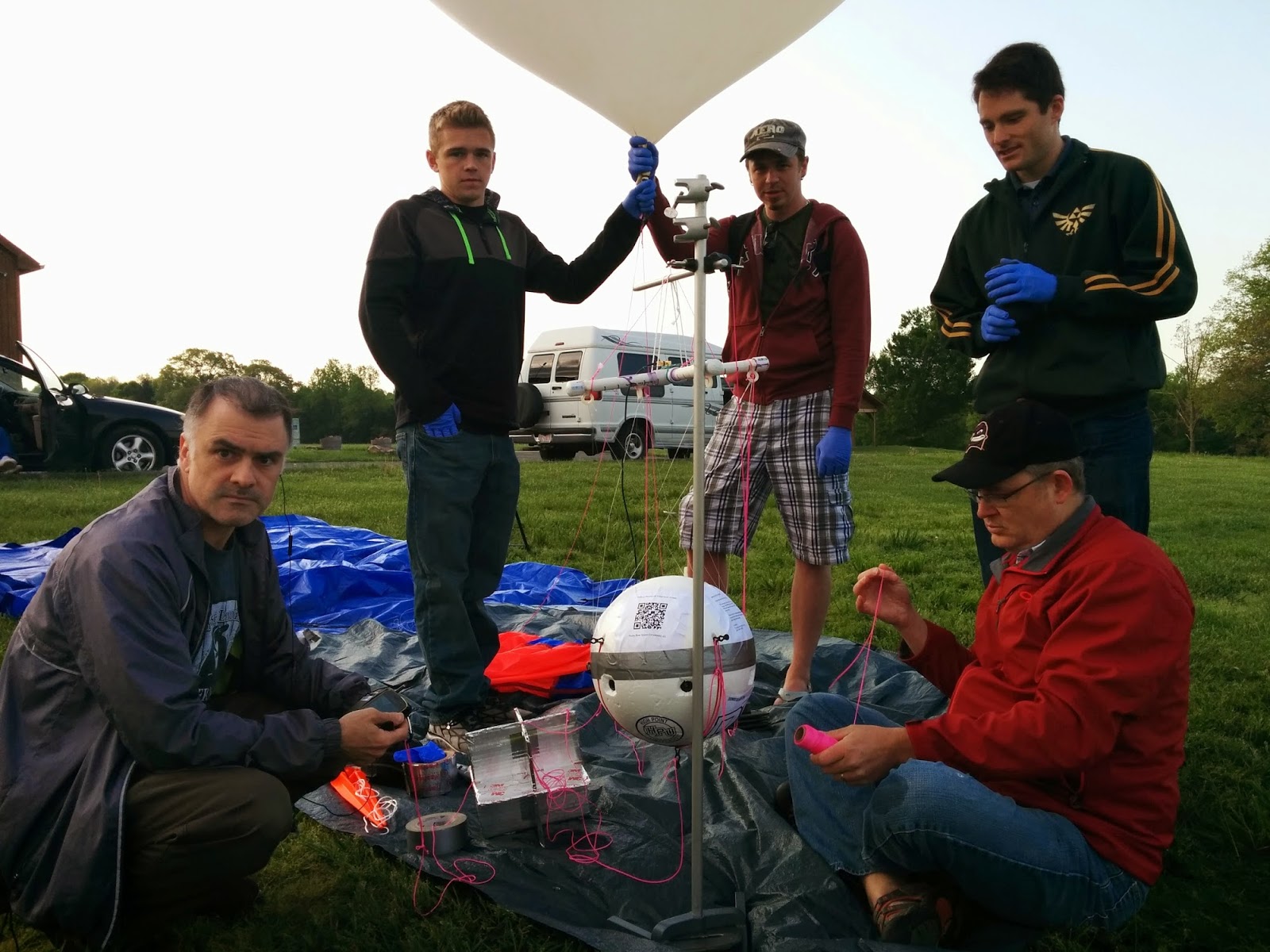
Team Near Space Circus HAB "NSC01" ready to launch

Done

  • Sending micro controllers into near space to take measurements? Done.
  • Sending a raspberry pi with a camera module into near space? Done.
  • Sending multiple gopros into near space? Done.
  • Taking pictures from near space? Done.
Anything left to do that hasn't been done?

Genesis of NSC01


One would think there is nothing left to do that has not been done before. Really, launching weather balloons for gathering data and taking high altitude pictures has been done many thousands of times before, even well before the age of the digital camera.

In fact, in NASA technical memorandum TM X-2208 published in 1971, it covers flights done in the later part of 1969 by the Langley Research Center in Virginia. This served as inspiration as to part of the payload for our own launch, an homage if you will. In this flight, they used medium format film cameras, both in the visible spectrum and the infrared.

So we started with that concept, we will have a Raspberry Pi with an infrared (PiNoir type) camera, and another with a regular CSI camera. Plus a very analog tech which I'll cover in Part 3.

And we quickly realized that we just opened Pandora's box... Innovation was possible everywhere we looked.

Eye in the sky


In my collection of Raspberry Pi related stuff, I had a few cameras already, including one infrared with an S-mount and lens. For a first flight, we could have simply gone with that and a regular raspberry pi camera (with its neutral lens which is not bad at all quality wise; neutral lenses are relatively easy to make compared to wide or tele lens). But we really wanted a wider shot, particularly as the 1080p video is cropped and gives even less coverage.

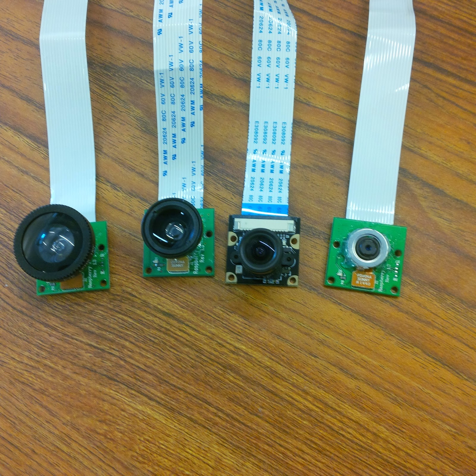
I didn't want to destroy the other modules to add the S-mount (commonly used on CCTV cameras), so I opted instead for a magnetic mount with a conversion lens. That way the camera can be used without conversion lens, or with a telephoto, wide or even a fish eye conversion lens.

Fish eye, wide, S-mount and magnetic mount RPI cameras

Of course, most people discard conversion lens as junk. And optically, they are terrible, with lots of barrel distortion and other issues. In fact, barrel distortion is easy to see on videos on youtube taken with wide (it is the built in lens actually) lens "extreme sports" type of video cameras that are so popular. The closer to the edge, the more it distorts.

But this was not going to be a show stopper for us. With the right software, I was convinced we could get some really decent shots. So I mounted a camera with a wide angle lens on top of the raspberry pi case, powered the pi with my phone spare battery pack (with a micro USB lead) and took pictures to calibrate my software (written in Python) and then went downtown Winston Salem to take pictures of buildings with lots of horizontal and vertical lines. Distortion is easily seen there.

And the results were quite nice:

Raspberry Pi camera with low cost wide angle, software corrected


What is left is the normal angling of lines due to perspective, but barely any lens distortion. Nice. Now let's move on to the computer.

Like groceries


So, a HAB with a few computers is like doing groceries for a family with a few kids. The more kids, the more expensive it gets. A single Raspberry Pi model A+ is only $20 plus shipping. And we knew from day 1 that we would use two of them. At a minimum.

Then we started looking at options to mount 4 cameras on the payload. For 360 panoramic pictures... Well, with the wide angle lens we used we'd need 5. But 6 is a nice round number, and due to crop factor of the 1080P mode, just making 360 degrees. How to connect 6 CSI cameras to 2 Raspberry Pi?

Plan A was building or buying a multiplexer. But time ran out for building, and we couldn't buy a real multiplexer. We did have a CSI switcher (made for 4 cameras per board) that I had ordered from Turkey. I had it in hand, but it never did work. I tried to get a replacement but the vendor never contacted me back. Caveat emptor.

Plan B was 1 Raspberry Pi per camera. And we had 6 regular cameras for the 360 panoramic, and 1 infrared CSI camera facing downward. So 7 Raspberry Pi it is...

Imagine your grocery bill with 7 kids...

Micro SD in their numbered SD adapters to avoid confusion

And so it went for our project. 7 Pi, 7 cameras, 7 micro sd memory cards (a mix of 32GB and 64GB cards), enough battery power for all of that. Oh yeah, power...

12V != 5V


We figured that for all the gear we would have onboard (7 Raspberry Pi, 7 CSI cameras, 1 USB camera, 2 GPS, sensors, 1 APRS transmitter doing 10W bursts every 2 minutes), we would use 3S (3 cells is series) Lithium Polymer batteries, commonly used in RC and drone applications.

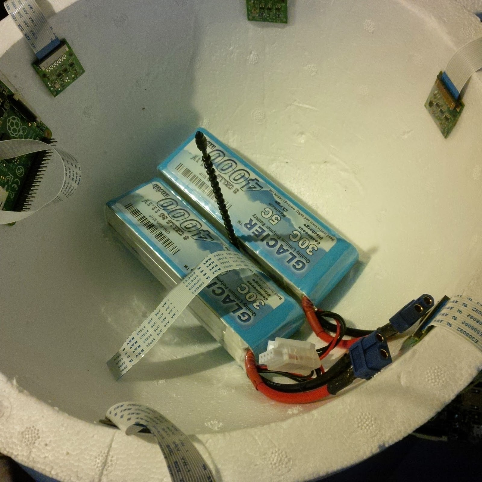
Two 3S 4000 mAh LiPos with XT60 connectors; cameras

We went with two, in order to make it easier to distribute the weight and redundancy. But that meant connecting them together in parallel. This was perfect for the APRS transmitter (transmitting our location, voltage and temperature every two minutes) as it expected a 12V source.

The two LiPo batteries connect on this side

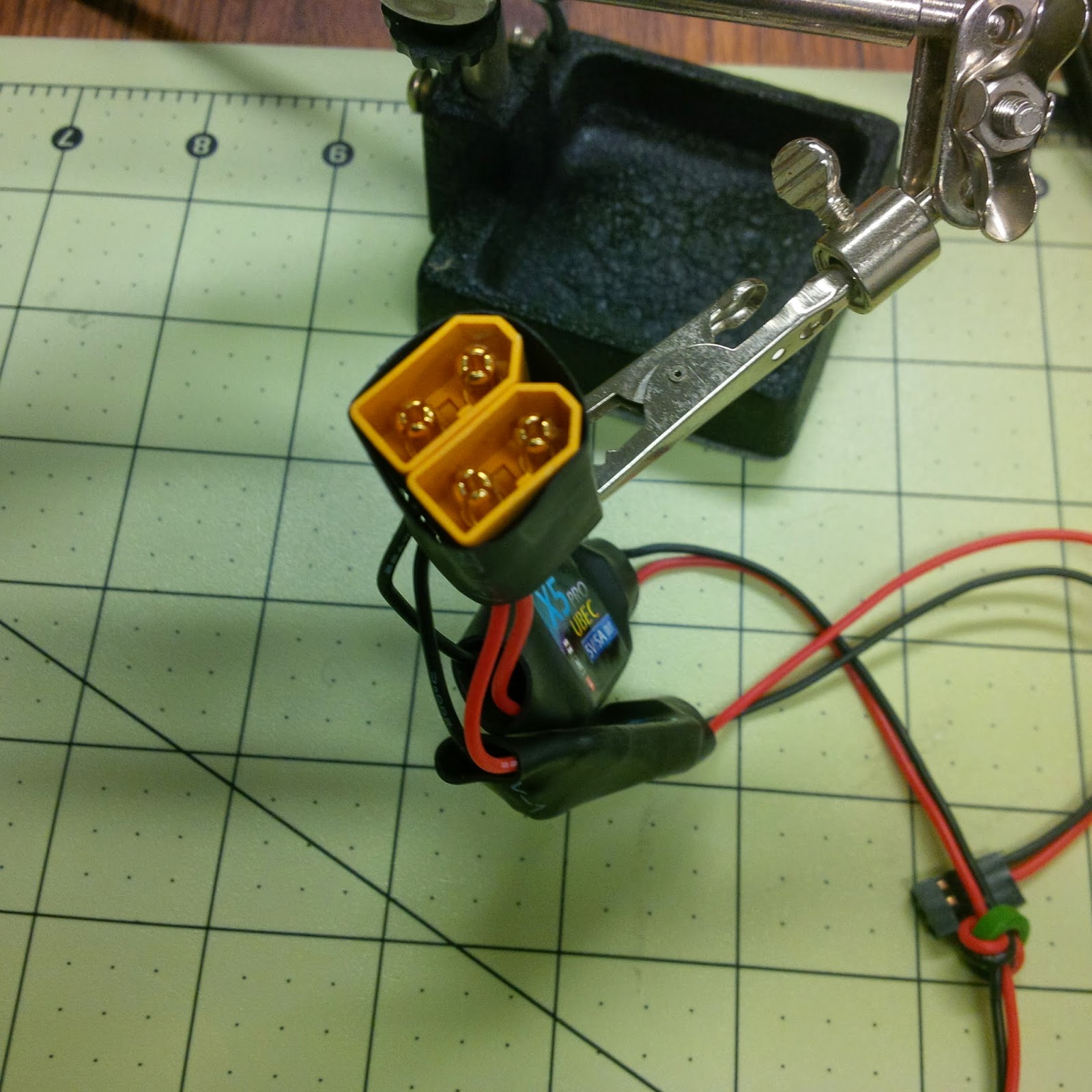
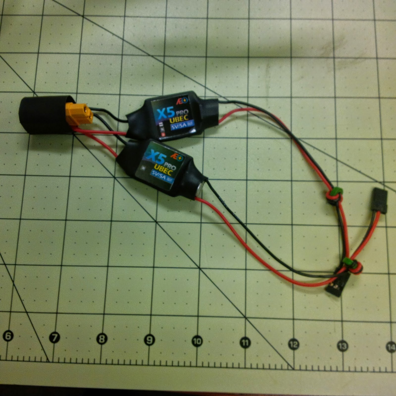
But the Raspberry Pi expect 5V, not 12V. So we added two UBECs. These are switching voltage regulators. They are not really designed to run in parallel, but we ran them for 12 hours straight many times with no issues. Look on RC forums, people say you cant do it. Well, you can. They do lose some of their efficiency that way, because they use PWM to regulate their output and measure their output as part of that. When 2 are in parallel, the output of one interferes some with the feedback loop of the other. Still, we were ok to lose some efficiency for redundancy.

5V UBECs (switching, not linear)
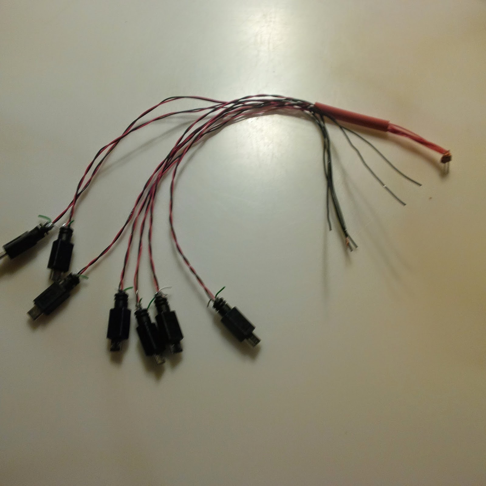
And we needed an octopus loom with 7 microusb to distribute the 5V to the 7 Raspberry Pi. It's about as light weight as we could make it... We did try to connect directly to GND and 5V on the GPIO header, but when it came time to network the 7 Pi together, it caused some issues. I'll talk about that in Part 2.

Power distribution to 7 Raspberry Pi

Where is the network?


I did say we had a computer network we were sending into space, didn't I?

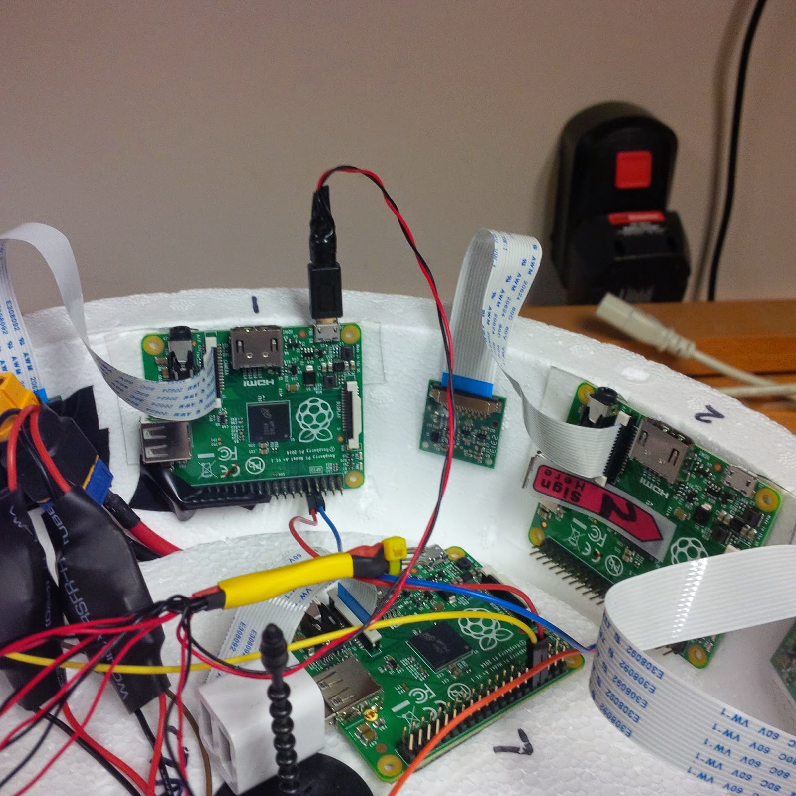
Raspberry Pi #1, 2 and 7

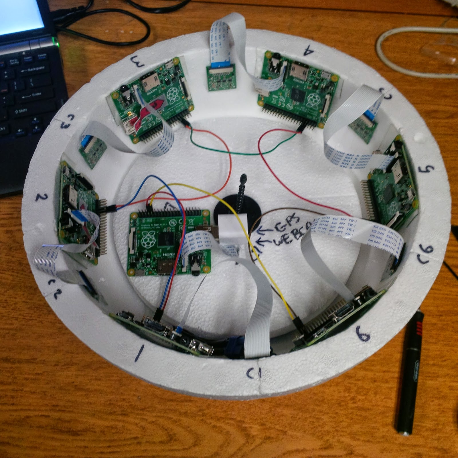
And I'll leave you today in conclusion of part 1 with a shot of the 7 Raspberry Pi networked inside the payload.

All 7 Raspberry Pi before the power wiring harness is put in place


Part 2 will go into the details of the network itself (article is now up: http://raspberry-python.blogspot.com/2015/04/the-computer-network-in-space-part-2.html), the master/slave component and the deadman's switch (now up, also) and part 3 will talk about the data gathering aspects. And in the interim, try to guess how we are networking the 7 Raspberry Pi.

And you can track our first launch progress (and real time data on the day of the launch) by keeping an eye on #NSC01 on twitter, following @pyptug or myself.

Francois Dion
@f_dion
[Update: added links to part 2 and to the deadman's switch]