Showing posts with label 3d. Show all posts

Sunday, December 13, 2020

Stereoscopic computing: anaglyph sprites on the Commodore 64

This article is part of a series -- you can read other entries

In our first 3D article we talked about the various types of stereoscopy available on computers. Modern systems can both generate a 1080p image and/or (with most video cards) a high-refresh-rate image, and most 3D displays or 3D-capable TVs are 1080p, so depending on whether you have an active or passive display system you can either use fast refresh (like my 120Hz DLP projector, which delivers a full 60Hz to each eye with active glasses) or an interlaced image and polarization (like my Vizio 3D TV and Mitsubishi Diamondcrysta monitor). This generates a high-quality, (usually) flicker-free high definition 3D picture.

However, classic computers invariably don't have either of those options, so we must resort to less satisfactory approaches. While some systems implemented a spinning shutter wheel as an active 3D display option, many older systems lack sufficient refresh rates to be sufficiently smooth and very old machines can't update the screen fast enough between eye views anyway. (That gives me a headache just thinking about it.) For most situations the typical choice will be either anaglyph, i.e., red-cyan glasses, or exploiting the Pulfrich effect. The latter, though not general purpose due to how the effect is generated, can be sufficiently convincing with the right application and we'll look at that in a later article. A third option is possible with modern displays but it, too, will be the subject of a later post. Today we'll try to get a primitive anaglyph effect working on the Commodore 64, and we'll do it with the classic and widely available red-cyan glasses you can get on Amazon or from specialty shops like Berezin (no affiliation, just a satisfied customer).

The basic concept with anaglyph is that the coloured glasses filter certain wavelengths of light, delivering different views to each eye. Since the red filter is over your left eye, your left eye only gets red (primarily), so the image that should be delivered to the left eye is tinted red. Likewise, as the cyan filter is over your right eye, the cyan filter should optimally admit only what is part of the right eye image. In practice, as anyone who's looked at anaglyph images knows, the strategy is imperfect: most full colour images will have some bleed-through and while colour selection and processing can reduce differences in brightness between the eyes, some amount of ghosting and retinal rivalry between the two sides is inevitable. Still, anaglyph 3D images require no special hardware other than the glasses and some well-constructed images can be very compelling.

To make objects stick out, the left (red) channel is separated further and further to the left from the right (cyan) channel; to make them recede, the left channel is separated further and further to the right. When the channels overlie exactly, they are seen at a neutral distance from the viewer as appropriate to the image's composition. The mnemonic is thus the three R's: red right recedes.

Unfortunately, conventional colour anaglyphs are difficult on a system like the C64 because there is only one fixed, limited palette and the shades available may not correspond well with the lens colours. You may be able to make the displayed colours more appropriate for your glasses by messing with the display settings or colour balance, but this naturally has other side effects. Additionally, there is no alpha channel, so overlaying objects (which is necessary to deliver two views in one image) just obscures what's behind them. Usually you would use a proportional shade of purple to deliver an appropriate level to each eye but the C64 has but one shade of purple, and you would have to manually figure out when to use it.

A way around the latter problem is to either dither or (as a special case of dithering) interlace. This reduces resolution but eliminates having to do costly alpha calculations and screen updates. One way of doing a 3D anaglyph display on a C64 is alternating red/black and blue/black lines in multicolour mode, as the red (VIC-II colour 2) and blue (VIC-II colour 6) shades are the closest shades to most red-cyan glasses. This gives you effectively a 160x100 monochrome image. For greater dynamic range you could also consider red/pink/black and blue/light blue/black on alternating lines, using black as the common background colour, and some of the CPU-assisted modes like FLI and Hires FLI can do even better. But this requires substantial precomputation to generate the image and thus is only generally useful for static images. How might we do this for a dynamic display?

While computers like the Amiga have playfields for overlaid elements, the VIC-II chip in the C64 really only has one option: sprites. Sprites do effectively have an alpha channel, but it is a single bit, so there is no translucency. Thus, if we want a dynamic 3D anaglyph display on the C64, a straightforward means is to interlace a blue sprite and a red sprite, yielding a composite 3D plane that can move in the Z-axis by changing their relationship to each other. And that's what we'll do here.

The illusion of depth is enhanced not only by the shift between the left and right channels, but also the size of the object, so we will need a routine to scale a sprite. For simplicity we'll just use a solid square block, which we can generate on the fly. Sprites on the C64 are 24x21, each row three bytes in length, up to 63 bytes in size. We will write a quick little utility routine that will turn a number into a string of bits, and then copy that to the same number of alternating lines, clearing the rest of the sprite so we can grow and shrink it at will.

The assembler source for this quick interlaced sprite scaler is on Github and can be cross-assembled with xa. We'll put the sprite at 832 ($0340) in the cassette buffer, which appears as SPRITE in the text. Here's some highlights.

        jsr $aefd
        jsr $ad9e
        jsr $b7f7
As a convenience for playing around in BASIC, these calls accept a comma after the SYS statement followed by an arbitrary expression, and then convert the result to a 16-bit integer and store it in $14 and $15. We only care about the low byte, so $14 is the entirety of the value. We clear the top row of the sprite, and if the parameter is zero, just copy that to the rest of the sprite (clears it). Otherwise, let's make enough one bits in the top row of the sprite by setting carry and rotating it through:
        ; turn x into x 1-bits
lup1    sec
        ror SPRITE
        ror SPRITE+1
        ror SPRITE+2
        dex
        bne lup1
We then duplicate it on alternating rows (unless it's 1x1 or 2x2).
        sbc #0 ; ror cleared carry, so -1
        lsr
        beq clrs ; no copies

        tay
        clc
lup2    lda SPRITE
        sta SPRITE+6,x
        lda SPRITE+1
        sta SPRITE+7,x
        lda SPRITE+2
        sta SPRITE+8,x
        txa
        adc #6
        tax
        dey
        bne lup2
And then we clear the rest of the sprite. We assemble this to 49152 and load it, then set some parameters. After you load the binary into VICE from wherever you assembled it to (and remember to type NEW after loading), you can cut and paste these POKEs into VICE.

poke53281,0:poke53280,0:poke646,12:poke53287,6:poke53288,2
poke2040,13:poke2041,13:poke53271,3:poke53277,3
poke53248,150:poke53249,100:poke53250,150:poke53251,102:poke53264,0
sys49152,10:poke53269,3

You'll get this display.

We have set the sprite colours, made them double size for ease of use, and positioned them so that they are interlaced. If you put on anaglyph glasses at this point, it's just a block at neutral distance. Let's write a little BASIC code to move them around as a proof of concept. You can cut and paste this into VICE as well:

10 rem midpoint at x=10
20 forx=0to20:poke53250,160-x:poke53248,140+x:poke53251,110-x:poke53249,108-x
30 sys49152,x:for y=0to50:next:next
40 forx=20to0step-1:poke53250,160-x:poke53248,140+x:poke53251,110-x
50 poke53249,108-x:sys49152,x:for y=0to50:next:next
60 goto 20

With glasses on, you will see the block swing from receding into the distance and protruding into your view by sliding and scaling.

There are two things to note with this primitive example. The first is that the steps end up separating the red and blue components quite a bit; combined with the afterimage from the bleedthrough, we end up seeing two blocks at their furthest extent. We can solve that problem by separating the sprites at a slower rate (say, half) than the scaling rate. This limits how far the composite plane can be moved in the Z-axis, but there are usually other optical limits to this generally, so we're not losing as much as one would think.

The second thing to note is it's kind of jerky because it's not updating the sprite registers fast enough (the delay loop is just there so you can see each step of the animation; the lack of smoothness is because of the computations and POKEs necessary on each "frame"). We'll solve this problem by rewriting the whole thing in assembly language. For style points we'll add a background (a crosshatch) as a neutral plane, and flip the sprite priority bits for the composite plane as it moves forward and back so that it also has proper occlusion.

The assembler source for the "complete" demo is also on Github (and also cross-assembled with xa), but notable parts are discussed below. We will write it with a small BASIC loader so we can just LOAD and RUN it.

        .word $0801
        * = $0801

        ; 64738 sys2061

        .word $080b
        .word $fce2
        .byte $9e, $32, $30, $36, $31
        .byte $00, $00, $00
The motion routine is more or less a direct translation of the BASIC proof of concept except we will separate the sprites by only half of the scaled size for less of a "double vision" effect, so we change the constants to match. Here VALUE is still $14, which we're still using merely as a holding location even though we are no longer servicing BASIC directly, and HVALUE is a free zero space location for the temporary result of the math.
mlup    lda VALUE
        clc
        lsr
        sta HVALUE

        lda #150
        sec
        sbc HVALUE
        sta 53250
        lda #110
        sbc VALUE
        sta 53251

        lda #108
        sbc VALUE
        sta 53249
        clc
        lda HVALUE
        adc #140
        sta 53248
At the end we wait a couple jiffies so that the animation is actually visible, check for RUN/STOP, and if not pressed cycle the position in VALUE back and forth. MODE is $15, since we don't use it for anything else either here, and is initialized to zero when we start.
        ; wait two jiffies per frame
        lda #0
        sta $a2
waitt   lda $a2
        cmp #2
        bcc waitt

        ; check run/stop
        lda 203
        cmp #63
        bne cycle
        lda #0
        sta 53269
        lda #147
        jmp $ffd2

cycle   lda MODE
        bne decr

incr    inc VALUE
        lda VALUE
        cmp #21
        beq *+5
        jmp mlup
        sta MODE
        ; fall thru
        
decr    dec VALUE
        lda VALUE
        cmp #$ff
        beq *+5
        jmp mlup
        lda #0
        sta VALUE
        sta MODE
        jmp mlup
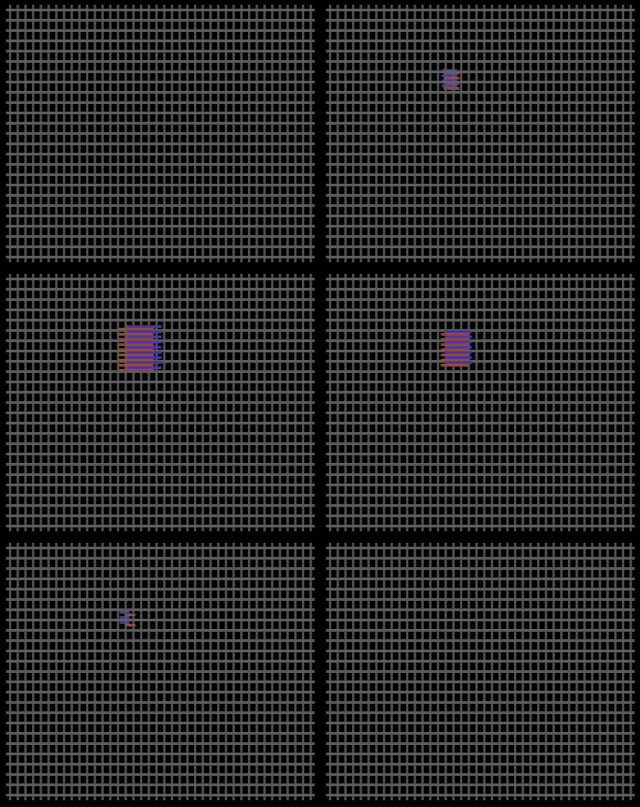
Here is an animated GIF of the result you can view with anaglyph glasses, though the result in an emulator or on a real C64 is smoother.

As you can see, the composite sprite recedes and protrudes appropriately, and depth cueing is helped by flipping the priority bits as it goes past the "zero" point (the crosshatch) where VALUE, in this coordinate system, is defined as 10.

While an anaglyph composite sprite approach clearly has drawbacks, it's still in my opinion the best means for independent motion of planar objects in the Z-axis and gives the most flexibility for "true" 3D on classic machines of this era. But the Pulfrich effect doesn't have its colour limitations and can be useful in certain specific situations, so we'll look at that in the next article.
Sunday, October 4, 2020

Stereoscopic computing: converting Quake and Doom

This article is part of a series -- you can read other entries

In our first 3D article, we talked about the basics of stereoscopic computing, including anaglyph rendering and active versus passive displays, and demonstrated a tool for turning a twinned set of webcams into a 3D image.

Games, of course, are the most obvious application, but early 3D games mostly dealt with the phenomenon as overlapping 2D planes due to the lack of 3D acceleration, limited CPU power and the predominance of 2D sprite hardware in contemporary video chips. These almost all used anaglyph colours (red/cyan glasses and others), but a few exploited the Pulfrich effect, and we'll look at some examples of these with the Commodore 64 in a later post. Even true stereoscopic systems like the Virtual Boy still largely used scaled planar images rather than true 3D graphics even though their separated video pathways yielded much better results (and eyestrain). As our previous article discussed, we try to avoid anaglyph rendering because all of them have some level of colour distortion (because they use colour differences to deliver a different picture to each eye) and ghosting (because that process is imperfect), and Pulfrich rendering, for reasons we will discuss, has only limited applications. For these examples, we will continue with my trusty Mitsubishi Diamondcrysta RDT233WX-3D, a passive polarized 3D display, though this should work for any passive 3D monitor or television. The general principles also apply to active systems like Nvidia 3DVision, though the details will be peculiar to each particular vendor-proprietary system.

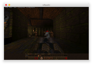
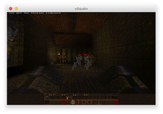
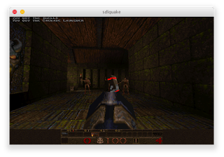
One of the earliest games to have a true 3D mode built into it was id Software's Quake, and, perfect for alternating line polarized passive displays, it interlaced the left and right eye views. However, it was actually created for active glasses alternating between left and right views in sync with the alternating scans of a CRT monitor (here is one such scheme), though this method can still be simulated with a line blanker with modern display cards and LCD panels. This code persisted into early source ports of Quake when id released the code under the GPL, such as in the software-rendered SDLQuake, and is enabled by going to the console and entering lcd_x 1 (the higher the value, the greater the stereo separation). SDLQuake can still, with some effort, be built on modern systems but is strictly limited to 640x480. Naturally, interlaced images will not appear in 3D on a 2D monitor, and may need to be downloaded and moved to the right vertical position to match the polarization order of your screen. For reasons that will become clear in a moment, these were captured during demo playback and could not be paused, but they still serve for purposes of comparison even though the scenes are not exactly identical.

lcd_x 0 (default, 2D only)

lcd_x 1

lcd_x 5

The highest stereo separation yields great effects for most of the display but makes the weapon uncomfortably close, which even without 3D glasses you can tell by how widely spaced the left and right views of it are. For my money the game is really only playable at the lowest separation setting, except that on modern 64-bit systems, SDLQuake and other early releases are not playable at all; they crash immediately when trying to start a new game because they are not 64-bit aware.

Modern Quake ports have corrected this problem but in turn have eliminated much, if not all, of the original stereoscopy support. A few have secondarily added back 3D using alternative means. One such port is Quakespasm, a continuation of the older Fitzquake, which in turn descends from id's GLQuake. Unfortunately, it only has an anaglyph mode (set r_stereo to a non-zero value in the console) and the old interlaced mode is gone. Let's fix that!

Pure software rendering would deal with this problem by taking two images and going to bottom copying one view to odd lines and the other to even lines. A faster approach on systems with SIMD is to blit over one screen entirely using those nice fat vector registers and then line in the other appropriately, which is the approach we took in Camaglyph. However, this is using OpenGL, so we have an additional option of using the stencil buffer. A stencil buffer approach would draw alternating lines in the stencil buffer and then map the left view and right view depending on whether there's a line in the stencil buffer or not. GLQuake does not itself make use of the stencil buffer (too early) and Quakespasm only uses it to prevent intersecting shadows, so we can easily remove that small amount of code to have exclusive control of the stencil buffer since the shadow intersection code is infrequently of rendering relevance.

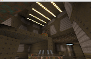
I don't claim this to be the best way of accomplishing it, but here's my patch against current versions. You will, of course, have to build it yourself from the source code. To enable it, go into the console (usually the tilde key) to set the appropriate options. r_stereo, same here as in regular Quakespasm, sets the stereo separation. I wouldn't make this much higher than 2.0; even that gave me a little bit of a headache, but since it's helpfully a float value 1.5 (in the console, type r_stereo 1.5) is a nice compromise since 1.0 doesn't really have enough depth. To enable interlacing, set the new cvar r_stereomode to either 2 (L-R) or 3 (R-L: my Diamondcrysta is R-L), or set it to 1 for the old red-cyan anaglyph. Because it allows larger screen displays the 3D-enabled Quakespasm is much more immersive and is really quite fun to play. For this screenshot I set the separation to a value of 2.0 so that the effect is a little more exaggerated.

This should work on any system (Mac, Windows or Linux, which is my usual environment) and on any graphics card of vaguely recent vintage.

I mentioned Doom in the title, which is more "2.5D," and mixes flat sprites (characters, objects) with 3D environments. There are many modern ports of this but the one I've come to recently enjoy is GZDoom, which as a built-in feature now has row interlacing as well as many other 3D modes in current releases of its renderer. To do this, pull down the console (tilde key) and enter vr_mode 12. Row interleaving in GZDoom is L-R, so I also add vr_swap_eyes true to make it R-L. You can also add this to gzdoom.ini wherever your system stores it (on Linux, ~/.config/gzdoom/gzdoom.ini). Because it tries to centre the window by default, however, I made a tiny patch to force everything to the 3D monitor which I use as a second, spanned display.

In future articles we will explore 8-bit ways of achieving 3D, and consider an alternate approach for when you want to convert a game to stereoscopic 3D but it's already using the stencil buffer.

Sunday, August 30, 2020

A second look at computer stereoscopy with the Minoru 3D webcam and Camaglyph

This article will be part of a series -- you can read other entries

Did you see what I did there? I'm proud of that title. Thank you very much.

Is 3D vintage computing? Well, it's complicated. 3D in computing didn't really have much traction in the early microcomputer age because of the limited palette, resolution and computing power: it was hard enough generating one image, let alone two and then figuring out ways to merge them. (I have some ideas about that but more later.) Apart from colour anaglyphs, best known as the red-blue glasses method, early stereoscopic computing was generally limited to active technologies (i.e., show one eye and then show the other), and the slower switching rates made this a rather flickery, headache-inducing affair. While some higher-end video cards like the Nvidia Quadro FX 4500 in my Power Mac Quad G5 (circa 2005-6) have connectors for active stereo glasses -- in this case a 3-pin mini-DIN -- almost all of these were proprietary and very few software packages supported it. Worse, these glasses wouldn't work with flat-panel LCDs, which were already displacing CRTs by then, because of the higher refresh rates required. There were some home gaming products like the Sega Scope 3D for the Master System, plus the infamous Nintendo Famicom 3D System and Nintendo Virtual Boy, but these only succeeded in showing the technical infancy of the genre and possibly increasing local referrals to ophthalmologists. (I'm intentionally ignoring lenticular and Pulfrich stereoscopy here because of their limited applications.)

IMHO, stereoscopic computing didn't really hit the mainstream until the advent of Blu-ray 3D, which increased, at least temporarily, the home market for polarized LCD displays that could show 3D content using passive glasses. Colour anaglyphs are neat, and can be done well, but they necessarily interfere with the colour palette to ensure that each eye gets as separate an image as possible (even tricks like Dolby 3D do this, though usually imperceptibly). Although active displays are still a thing -- my 3D home theatre is DLP, and uses DLP-Link, which are 120Hz active glasses -- they're also heavier and have to be powered, and active display solutions are overall more expensive. Passive LCD 3D screens, however, were for at least a few years plentiful and relatively inexpensive, and most TVs of a certain vintage came with the feature when it was thought 3D would be the next big thing. 3D movie cameras powered many major studio production shoots and 3D movies were plentiful in consumer stores. Many games for contemporary consoles, notably the Xbox 360 and PlayStation 3, offered stereoscopic gameplay, and you could even buy computer monitors that were 3D. My secondary display is a Mitsubishi Diamondcrysta RDT233WX-3D, which is an exceptionally fine IPS passive display I ended up importing from Japan, but there were many manufacturers on both shores.

Well, those days have died. If you look at Wikipedia's list of stereoscopic video games, which is a good summation of the industry, there is a dramatic falloff around 2014. Most 4K TVs in the United States don't offer a 3D mode of any sort, partially for technical reasons I'll mention, and only a subset of console games still support stereoscopy. Many players will still play them but Blu-ray 3D movies are all but gone from the American market. While movie theatres still offer(ed) 3D showings, COVID-19 has kind of crushed that industry into little tiny theatre bits, and very few major motion pictures are filmed in native 3D anymore. I think it's safe to say that until such time as the fad revives, as fads do, stereoscopic computing has retreated back to the small realm of enthusiasts.

And, well, I'm one of them. I'm not as nuts as some, but in addition to the Diamondcrysta monitor I have a 3D home theatre (using DLP and DLP-Link glasses), a Vizio 3D TV, a Nintendo 3DS and a Fuji FinePix Real 3D W3 still and video camera. I've got heaps of Blu-ray 3D that I imported at sometimes confiscatory rates, but happily most of them are all-region. I'm pretty much on my own for software, though, so I figured writing a simple display tool for a 3D webcam was a good place to start with writing my own stereoscopic applications. And there's one available very cheaply on the remaindered market:

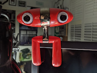
This device is the Minoru 3D webcam, circa 2009. Despite the name (it means "reality" in Japanese), the device is actually a British creation. It is not a particularly good camera as webcams go, but it's cute, it's cheap and it's 3D. However, it only comes with Windows drivers, and they don't even work with Windows 10 (probably why it's so cheap now). My normal daily driver is Linux. Challenge accepted.

The Minoru appears to the system as two USB Video Class cameras in a single unit connected by an internal hub; lsusb sees the two cameras as Vimicro Venus USB 2.0 devices, which is a very common USB camera chipset. Despite the documentation, the maximum resolution and frame rate of the cameras is 640x480 at 30fps and the 800x600 mode advertised appears to be simply software upscaling. Nevertheless, when treated as separate devices, the individual video cameras "just work" with Video4Linux2 in VLC (the "eye" lights up when it's viewing you), so what we really need is something that can take the two images and merge them.

The Minoru's included drivers offer a side-by-side mode but most people will run it in anaglyph mode. Appropriately, it comes with a metric crapton of cardboard glasses you can give to your friends so they can see you in all your dimensions. There are many colour schemes for anaglyphs but the most common is probably red on the left lens and blue (or preferably cyan) on the right, and there are many algorithms for doing that. I wrote a simple V4L2 backend that runs both camera sides simultaneously and pulls left and right frames with an SDL-based frontend as the visualizer, and then selected two methods that are generally considered high(er) quality.

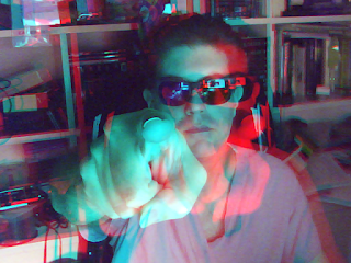
The first, the optimized anaglyph method, is quite straightforward to implement: for the merged image, use the green and blue channels from the right image, and compute the red channel of the merged image using 0.3 of the left image's blue channel and 0.7 of the left image's green channel. (Some versions of this boost use a 1.5 factor prior to merging them, i.e., a 50% boost, which helps with dimness, but means the resulting value needs to be clamped.) This has the effect of dropping both images' red channels completely but the eye can compensate somewhat, and the retinal rivalry between eyes is reduced compared to more simplistic methods. A SIMD-friendly method of doing this is to simply copy the entire right image to the merged image, and then overwrite the red channel in a separate loop. There is still a bit of ghosting but this sort of image can be rendered very quickly. Here is an optimized anaglyph image of yours truly from the Minoru, viewable with red-cyan glasses:

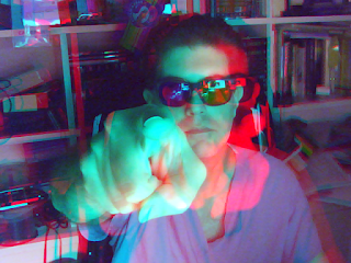
A superior and widely adopted anaglyph method is the one devised by Eric Dubois. His innovation was using a least-squares approach in the CIE-XYZ colourspace which can be approximated with precomputed coefficients, using matrix multiplication to merge the two images. It is slow to compute and requires saturation math to deal with clipping, and reds get turned into more of an umber (you can see this on what's supposed to be my red anaglyph lens), but the colour rendition is overall better and ghosting between the two sides is almost absent. Here is a Dubois image of me in almost the same position, also viewable with red-cyan glasses:

But anaglyph is just not satisfactory for good colour rendition even if you get accustomed to it, and even the best anaglyph glasses with good lenses and dioptres will still have some ghosting between sides on most colour images. This is where passive 3D comes in.

Most passive 3D monitors use alternating polarization, implemented as either a second glass substrate called a patterned retarder, or more recently using a film overlay (called, naturally, a film-based patterned retarder). Each separate line of the display alternates polarization, which without polarized glasses only shows up as a very faint linear interlace. My Diamondcrysta and Vizio passive 3D displays are 1080p, so with glasses off you get all 1080 lines, and with glasses on 540 lines go to one eye and 540 lines go to the other. (This is probably why 4K displays don't do this, other than cost: it would make upscaling 3D 1080p content lower quality because the horizontal lines cannot be interpolated or smoothed.)

This is obviously lower 3D resolution than an active display, where the entire screen (like on my DLP projector) alternates between each eye. However, the chief advantage to us as homebrewers is that the polarization is an intrinsic property of the display -- anything displayed on that screen is subject to it, rather than relying on some vendor-specific video mode. That means anything can display anything in 3D as long as you understand which lines will be activated by what you draw.

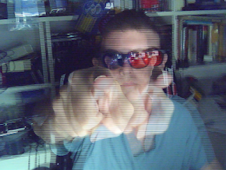
My Diamondcrysta is a R-L display (the polarization goes right-left-right-left-etc.), so starting with line 1 at the top, odd lines must show the right image and even lines the left image. This requires us to find out where the actual image is positioned onscreen, not just the position of the window, since window decorations will shift the image down by some amount. SDL 2.0 will tell us where the window is, but I'm using SDL 1.2 for maximal compatibility (I'd like to port this to my G5 running Mac OS X Tiger), so instead when we display the image we ask SDL for the underlying widget, get its on-screen coordinates, ask X11 how big the window decorations are and then compute the actual Y-position of the image. You could then draw the merged image by doing alternating memcpy()s line by line, but with today's CPUs with potentially big SIMD vector registers, I simply did a big copy of one entire view and then on every other line drew in the lines from the other view, which is noticeably faster. This yields the following image, which redraws itself with the proper lines in the proper places when the window is moved:

You'll need to view the full-size image (click on it). To view this on a passive polarized 3D display or a 3D TV acting as a monitor, you've got exactly a 50% chance that your web browser will already have it at the right Y-position. If it doesn't, you may want to save the full size image to disk, open it up on that display, and shift its window up or down pixel by pixel with your polarized glasses on until it "pops." Your monitor does not have to be put into any special "3D mode" for this to work.

The source code is in pure C, runs entirely in userspace, and should build on any Linux system (including big-endian) with V4L2 and SDL 1.2. I call it Camaglyph and it's on Github. It's designed to be somewhat modular, so once I sit down and write a QuickTime or QTKit grabber I should be able to make this work on my G5. I've included a configuration file for akvcam so you can use it as, you know, a webcam.

In future posts we'll look at converting classic games to work with stereoscopic displays instead of just having anaglyph modes, and explore some ideas about how we can get classic computers to display anaglyph 3D.