
Showing posts with label Engineering. Show all posts
Showing posts with label Engineering. Show all posts
Monday, 23 December 2019
Electromagnetic forces between busbars
Saturday, 19 October 2019
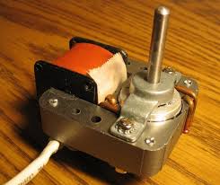
Shaded pole motor magnetic field simulation in FEMM
For a long time I wanted to simulate the electric and magnetic quantities in a shaded pole motor and last week I finally found 10 minutes to dedicate to this activity. I find these motors fascinating for their simplicity and for how they work by using the laws of electromagnetism.
Shaded pole motors are a variety of induction motors. They are quite the cheap type of motors: you can usually find them in old washing machines (powering the water pump for example) or even in new white goods where they may be used for periodic (but not frequent) tasks, for instance every 30s for turning a wheel. It is extremely rare to find a shaded pole motor that runs continuously. In the picture below (from Wikipedia) you can find an example of such motors.

Shaded pole motors are a variety of induction motors. They are quite the cheap type of motors: you can usually find them in old washing machines (powering the water pump for example) or even in new white goods where they may be used for periodic (but not frequent) tasks, for instance every 30s for turning a wheel. It is extremely rare to find a shaded pole motor that runs continuously. In the picture below (from Wikipedia) you can find an example of such motors.

Thursday, 16 August 2018
Automate your garden lights DIY style: getting practical!
This post is a follow up of this project.
After a lot of fiddling around, I finally built up the circuit for automating the turn on and off of my garden lights. It was about time wasn’it? Yeah, I know, it took me some time, but it was worth it since I think the end result is particularly nice and I enjoyed the process of building the circuit.
Goals of this project
The objectives of this DIY project are the following:
- Automate the turn on and off of garden lights: 4 LED lights powered from a battery which is recharged every day through an appropriately sized solar panel. The lights should turn on in the evening and turn off in the morning. Ideally turn on and turn off should be adjustable with ambient light.
- Improve my basic knowledge on how to design a proper circuit, a PCB, source components and debug analog circuitry.
- Keep the project relatively cheap.
The circuit in LTSpice
Below you can find a picture of the circuit simulated in LTSpice with all my notes following testing and a close up of the circuit.


Friday, 10 August 2018
IV characteristics of diodes
This week I finally got to play around a little with some electronic components I ordered and test them before using them on side projects. My goal was to find the IV curve of a 3V 0.5W zener diode I need to use on a project. Since I had all the instruments set up, as a bonus I decided to find the IV curve of a blue LED as well.
Test circuit and instruments setup.
The test circuit I used for the measurements is the following

Sunday, 4 March 2018
Calculating the DFT in C++
When you learn about the Fourier transform and what it can show you about a signal, you immediately start thinking about its possible applications. The Fourier transform, however, deals with continuous time signals while, in practice, computers deal with discrete time signals (i.e. a sampled version of the original continuous time signal). When it comes to discrete time signal, you can calculate a discrete Fourier transform to get the frequency content of the signal.

Saturday, 2 September 2017
How would you make a very simple and rotating magnetic field starting from a three phase power supply?
Recently I had a brilliant idea :D why not make a rotating magnetic field that can rotate a needle of a compass? (or any other magnetic needle for that matter).
Ok but the design must be very basic. One possible option would be the following:

Simulation of the electric field of a three phase cable using FEMM
Finding analytical solutions to physical problems is always nice and rewarding, however it can be a bit of a pain when the geometry of the problem (just to mention one possible hustle) becomes more complex than just a sphere, a cylinder or any other basic shape.
If you think of a simple cable, with a copper core and a PVC insulation, calculating the electric field generated in the insulation layer using pen and paper may still be feasible, however, using FEMM greatly improves your life when doing calculations as an engineer, student, or “just” curious person.
This simple cable can be modelled using FEMM as follows

The cable has a total diameter of 7 cm, with a first PVC insulation with a radius of 2.6 cm, a 0.05cm air gap and another PVC insulation layer.
If you think of a simple cable, with a copper core and a PVC insulation, calculating the electric field generated in the insulation layer using pen and paper may still be feasible, however, using FEMM greatly improves your life when doing calculations as an engineer, student, or “just” curious person.
This simple cable can be modelled using FEMM as follows
The cable has a total diameter of 7 cm, with a first PVC insulation with a radius of 2.6 cm, a 0.05cm air gap and another PVC insulation layer.
Friday, 1 September 2017
Magnetics simulation with FEMM
FEMM stands for Finite Element Method Magnetics, and it is a nice software for solving magnetics and electrostatics problems.
I’ve known FEMM for at least a couple of years but I’ve never tried it out and used it at its full power! Now the time has come to do that!

In this post I’m going to present the results of the following simulations:
- A C shaped electromagnet (detailed results).
- The magnetic field of the rotor of a 4 poles synchronous machine (brief overview).
Wednesday, 30 August 2017
Another typical control problem: balancing a ball on a beam
Balancing a ball on a beam is not a common problem you may face during your everyday life, however, this simple example of engineering can be extended to more complex problems and, in general, to other more interesting control problems such as
- Control of temperature in a room
- Control of robots
- Control of automated cars
- Control of industrial processes
The main problem tackled in this article is the design and implementation of a basic PID based controller to control the position of a ping pong ball on a beam. Ideally the controller should be able to set the position to whatever value of the x axis the user decides to apply. This is a simple scheme of the physical system

Modelling a DC motor using LTspice, Simulink and Matlab
Electrically speaking, a permanent magnet DC motor can be modelled as follows:

applying LKT we obtain the following differential equation
$$v = Ri+L\frac{di}{dt}+e$$
where $R$ is the equivalent resistance of the brushes plus the windings, $L$ is the inductance as seen from the external terminals of the motor and $e$ is the back EMF. Usually R is very small and can be difficult to measure with a multimeter. The back EMF can be expressed as a function of the speed of the motor $e = k\phi\omega$.
Thursday, 18 May 2017
Lighting your garden with LED lights and the sun: a DIY project, part 2.
Some time ago I wrote a short article on a small circuit I made to power on and off my garden lights using only a handful of components and some patience. Since then, however, I’ve dug deeper and found out some other good solutions to the problem.
A quick recap of the problem: At dusk and dawn I’d like my garden lights (powered by 12V DC batteries) to switch themselves on and off without me doing anything: a first step towards total automation ;)

My first try at accomplishing this task was using a simple BJT with a voltage divider specifically design to allow a certain bias current when it gets dark. See here for more information on this first raw trial.
Tuesday, 2 May 2017
Current sink: one of my first experiences with Eagle
I’ve learnt a few things the hard way while messing around with electronic circuits, here is a basic summary:
Wednesday, 30 November 2016
Short circuit currents calculation on high voltage lines
Short circuits are one of the most common failures that can happen when dealing with electrical circuits.

Short circuits can be accidental, think of a tree branch leaning onto a high voltage powerline or due to the breakdown of the isolating material (this is often the case as it gets older and loses its isolating property). Whatever the cause, short circuits are, for sure, an enemy of your electrical systems mainly because the following effects:
Wednesday, 23 November 2016
Solving electrical radial lines with Python
Electrical transmission systems are something we all take for granted. They work in a reliable manner ensuring high quality of service and as few minutes lost per year as possible.
Low voltage lines and most of medium voltage lines are radial lines, that is they are like a branch of a tree with a unique power supply location. Radial lines are relatively easy to work with, you can solve a radial line problem (ie you can get currents and voltages) by applying Boucherot’s theorem to each section of the line. This is a good news for a Python enthusiast as myself, since repetitive tasks lends themselves to be automated with programming.
Since Boucherot’s theorem uses the absolute values of electrical quantities, it is useful when you are working with AC lines and you would like to know the magnitude (rms) of currents and voltages while at the same time you do not really care about the phase differences. The rms values are used, for instance, when you need to choose the protection systems to install and what kind of electrical wires to use.
Suppose you are given the following three phase balanced radial line:

You can think of C1, C2 and C3 as industrial motors or any other kind of three phased balanced loads.
Sunday, 24 July 2016
Fluid Dynamics: Pressure Drop Modelling [heavily revised]
Some time ago I uploaded a short script on modelling pressure drop in a circular diameter pipe. While at the time I felt I did a good job, I knew there sure was room for improvement. After having attended a (very tough) course on fluid dynamics and applied physics, I feel a lot more confident on this topic and therefore I would like to share a little model I built for a project I am working on.

Monday, 15 February 2016
Simulating a mass attached to a spring with control theory
Control system theory is very useful when it comes to simulate physical systems and their behaviour.
Suppose you have a mass attached to a spring on an horizontal flat surface. The force diagram associated with this physical system can be sketched as follows:

By analysing the force diagram, you can actually see that on the x axis the only forces acting on the mass are the elastic force (Fe), the friction (Fr) due to the air resistance and the external force applied to the mass (u). On the y axis the normal force and the force of gravity balance out, therefore there is no motion.
Sunday, 14 February 2016
Solving a circuit with a mutual inductor using LTspice
Mutual inductors can be a lot of fun, and sometimes a bit of an headache if you mess something up or represent them in a complicated way. Take for instance the following circuit designed with Circuit Lab a great online circuit design and simulator tool

This is one of the first excercises we were taught in our circuit class. As you can probably see, the circuit is composed by two current sources with different frequency, some resistors and a mutual inductor. The aim of the analysis is to find out the total power consumed by the resistors. Let's analyse each problem carefully before proceeding.

This is one of the first excercises we were taught in our circuit class. As you can probably see, the circuit is composed by two current sources with different frequency, some resistors and a mutual inductor. The aim of the analysis is to find out the total power consumed by the resistors. Let's analyse each problem carefully before proceeding.
Tuesday, 22 December 2015
Step response of a RLC series circuit
Today I am going to make a brief description of the step response of a RLC series circuit. This is the schematic made with LTspice

As you can see the components used are a resistor, an inductor and a capacitor connected in series. By applying Kirchhoff voltage law we obtain the following equation
$$u(t) = R x(t) + L\frac{dx(t)}{dt} + \frac{1}{C} \int x(t)dt $$
Monday, 21 December 2015
Three-phase symmetric perfectly balanced system LTspice simulation
A symmetric, three-phase and perfectly balanced system can be easily modelled either by pen and paper with the use of phasors or using LTspice which is faster. In case you would like to try I suggest to first try the pen and paper way and then check the results on the simulator. A basic example of such system would be the following:


Tuesday, 8 December 2015
How to simulate a simple high pass filters on LTspice
Here I am again after a long break!
During my last engineering class I learnt about the frequency response of a system and how this thing can be applied to solve simple problems. But the crucial question from most of us was the following: how would you build such filters, and perhaps more importantly, how would you tune them?
In principle, you could build a simple filter using nothing more than a resistor and a capacitor and, as you might have guessed, LTspice once again comes at rescuing us from our wandering around.
Let’s say we would like to build a simple high pass filter. Then we could try building the following circuit
Subscribe to:
Posts (Atom)